What is A Load Profile in Test and Measurement?
 A load profile is a time-dependent record of the magnitude, direction, duration, and frequency of mechanical forces a test structure or transducer experiences during operation.
In test and measurement, selecting a load cell based solely on the maximum expected static force is a common engineering mistake. Static capacity accounts for only one dimension of a testing operation. A comprehensive load profile documents the complete mechanical lifecycle, capturing continuous static baselines, cyclical fatigue, rapid dynamic spikes, multi-axis moments, and recovery periods.
Analyzing a complete load profile ensures structural safety, maintains high measurement resolution, and protects transducers from premature fatigue or catastrophic over-range failure.
What Parameters Define a Load Profile
The pattern of load application during a test, such as single ascending, cyclic, tension, or compression, which influences the relevance of specifications such as hysteresis.
A rigorous load profile captures four primary parameters.
- Force magnitude and dynamic range include the baseline force, working force ranges, and peak transient loads. The ratio between continuous operating loads and instantaneous peak forces determines whether a sensor needs high sensitivity or a high mechanical overload margin.
- Duty cycle and frequency are the operational rhythm over time. This includes how quickly forces change, how long the load stays constant, and the cycling frequency (cycles per second).
- Vector and directional forces, whether the applied load is purely axial or includes side loads, shear vectors, off-center moments, or reversal through zero between tension and compression.
- Thermal and environmental timing: how mechanical loads correlate with thermal expansion, ambient temperature fluctuations, or continuous vibration exposure.
Key Load Profile Questions to Answer Before Selecting Sensors
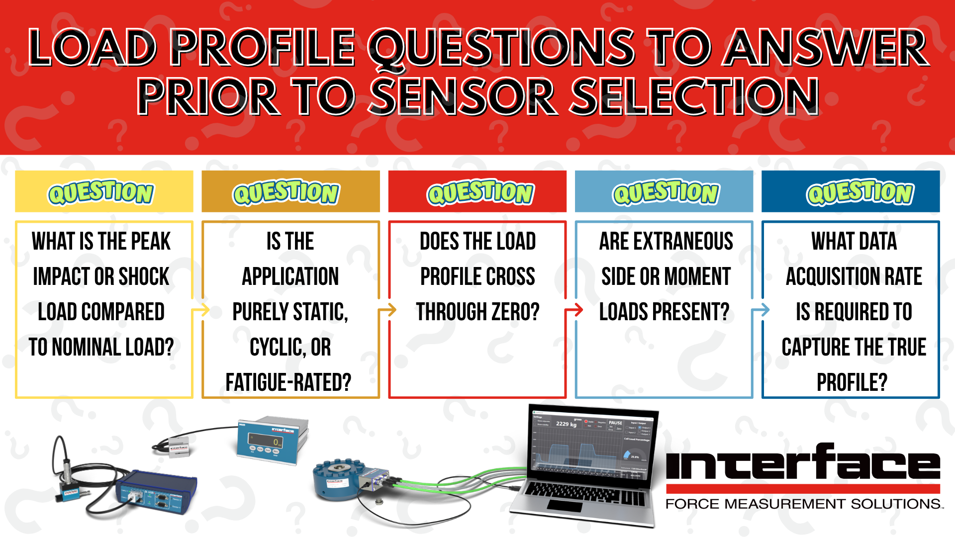
Before selecting a sensor, hardware, or finalizing a test stand design, engineers and technicians must thoroughly evaluate how mechanical forces behave in the test and measurement environment.
First, consider peak impact and shock loads compared to nominal capacity. High-speed actuators, material fracture events, or dropped masses often generate impact forces that can exceed static ratings by several multiples within milliseconds.
Next, evaluate the operational life requirements to determine whether the setup is purely static, cyclic, or fatigue-rated. While general-purpose load cells handle static or low-cycle applications reliably, applications exceeding hundreds of thousands or millions of cycles require dedicated fatigue ratings to avoid micro-fracturing in the flexure element.
Stress reversals demand equal scrutiny. If the load profile crosses zero and transitions between tension and compression, alternating mechanical stresses will accelerate wear on internal strain gages and threaded attachments, such as connectors.
Finally, examine extraneous forces and instrumentation capabilities. Real-world setups rarely apply axial force. Mechanical misalignment, thermal growth, and pivot movement introduce bending moments that can distort signal accuracy or damage flexures. At the same time, if high-speed impacts occur over mere milliseconds, standard industrial sampling rates will miss the peak entirely, recording an artificially low value.
Review: Expert Tips for Essential Load Cell Specifications for additional information on sensor selection.
Test and Measurement Load Profile Examples

Dynamic Cyclic Fatigue Testing
Aerospace component testing, such as an aircraft wing actuator or landing gear assembly, requires capturing millions of sinusoidal cycles between 10-80% of full capacity at frequencies from one to twenty hertz, with occasional static holds. The Interface LowProfile Fatigue-Rated Load Cells, including our 1000 Fatigue-Rated Universal LowProfile® Load Cell and 1100 Ultra Precision Universal LowProfile Load Cell series, are engineered to endure over one hundred million fully reversed cycles without zero shift or structural failure.

High-Impact Drop and Material Testing
Crash testing, material yield evaluation, and destructive drop testing produce an immediate force spike lasting only a few milliseconds, followed by a sharp drop-off and mechanical ringing. This profile requires Interface Miniature Beam or LowProfile Load Cells connected to high-speed data acquisition, such as the BX8 Multi-Channel Data Acquisition System, providing high natural frequency response and significant mechanical overload protection.

Automated Assembly and Press Monitoring
Robotic insertion, fastener driving, and press-fit manufacturing subject instrumentation to downward compressive axial force simultaneously combined with side shear loads and torsional moments. Applying single-axis load cells to this profile risks bending damage and off-axis errors. Interface 6-Axis Load Cells and 3-Axis Load Cells isolate axial thrust from side loads and moments simultaneously.

Continuous Static Monitoring
Silo, bin, and vessel weighing applications apply loads gradually and sustain them for hours, days, or weeks. Dynamic cycling is minimal, but the profile poses significant creep and zero-drift risk under sustained load. Interface S-Type Load Cells (SSM and SSM2 series) and A4200 and A4600 WeighCheck Load Cells provide the thermal stability, high-temperature compensation, and low-creep characteristics needed for repeatable static measurement over extended operational windows.
Load Profile Best Practices for Field Technicians and Test Engineers
Accurately characterizing a load profile requires close coordination between mechanical integration and signal acquisition. When sizing for continuous cycling operations, select a load cell rated for double the expected highest peak dynamic load to ensure strain gage fatigue remains well below the material endurance limit.
Where angular misalignment or thermal expansion cannot be eliminated mechanically, install rod end bearings, spherical alignment washers, or flexure mountings to isolate the transducer from damaging bending moments.
Ensure data acquisition instrumentation matches the load curve by setting sampling rates to at least ten times the highest frequency component of the applied force. Watch Interface’s Unlocking the Power of DAQ Webinar.
For millisecond impact spikes, high-speed sampling at thousands of samples per second is mandatory to capture true peak loads. Finally, mathematically calculated models frequently overlook real-world friction, system vibration, and hydraulic spikes. Always capture in-situ dynamic measurements during initial commissioning before finalizing permanent sensor specifications.
Technical Load Profile Consultation and Sensor Selection
Characterizing the full load profile is the most effective way to prevent premature sensor failure and ensure measurement precision.
Review your test specifications and operating data with Interface application engineers to identify the right transducer capacity, fatigue rating, and data acquisition hardware for your application. Contact the Interface engineering team to start a technical consultation for your next test program.
ADDITIONAL RESOURCE

Expert Tips for Essential Load Cell Specifications
Load Cell 101 and What You Need to Know
Selecting the Right Indicator for Test and Measurement Applications
LowProfile Complete Systems for Immediate Force Measurement Deployment
Test and Measurement Solutions