Fundamentals of Multi-Axis Sensors

Multi-Axis sensors are precision transducers designed to measure multiple forces and moments simultaneously. Unlike a traditional load cell that measures force in only one direction, a multi-axis sensor can capture the complete loading condition of an object in real time.

6-Axis Force/Torque Sensors

Forces and Moments

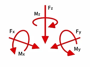
These 6A and 6ADF sensors are suitable for measuring forces and moments in the 3 directions of the coordinate system.

They consist of a total of 6 strain gauge full bridges.

The 6 measurement signals are provided via a 24-pin connector for further processing with a measuring amplifier.

A calibration matrix is required to calculate the forces and moments from the six measurement signals. The calibration matrix establishes the relationship between the six measurement signals and the forces Fx, Fy, Fz, and the moments Mx, My, and Mz ( Multi-Axis_Manual-1-7-2021-revised-03-16-26.pdf ). By using special calibration matrices ( Matrix Plus ), accuracy can be optimized and crosstalk minimized for a specific load case.

The calibration matrix is applied, for example, in the BX8 measuring amplifier, so that each measuring channel corresponds to a force or a moment via the USB interface or via the analog outputs.

(Channel 1: Fx, Channel 2: Fy, Channel 3: Fy, Channel 4: Mx, Channel 5: My, Channel 6: Mz).

To calculate the forces and moments, all 6 channels must be evaluated. The vector containing the 6 strain gauge signals is multiplied by a 6×6 matrix to obtain a vector (Fx, Fy, Fz, Mx, My, Mz).
3-Axis Force/Torque Sensors

The 3A and 3AR sensors are suitable for measuring forces in the three directions of the coordinate system. They consist of a total of three strain gage full bridges.

Unlike the multi-component sensor, the signal of each channel already corresponds to a force Fx, Fy, Fz.

The separation of the axes is achieved through the design and arrangement of the strain gauges. A measuring amplifier is required to amplify the signals to voltages or to digitize the signals for, e.g., the USB interface or the CAN bus.

Compact and precise

A multi-axis sensor can replace up to six single-axis sensors simultaneously. A 3-axis force sensor combines three single-axis force sensors into one component.

The accuracy achieved with a 3-axis force sensor or a six-component sensor cannot be replicated by combining three or six single-axis sensors. Conventional force sensors are sensitive to the “oblique” application of forces: a measurement error arises from the application of a force perpendicular to the actual measurement direction, which is often difficult to quantify precisely. When three force sensors are combined in series, one force sensor measures the load in three dimensions, even though it is designed for only one direction of load. Additionally, connecting sensors in series also results in a series connection (and thus a reduction) of spring stiffnesses. Conversely, attempting to separate the individual axes with linear guides introduces errors on the order of 10% or more due to static friction in conjunction with the short measuring ranges of force sensors.

3-axis force sensors and multi-component sensors offer the highest accuracy and stiffness with a simple and compact design.

Crosstalk

Applying a force or moment to one measuring axis also results in a reading on the axes perpendicular to it. This effect is called crosstalk.

For 3-axis force sensors and multi-component sensors, the crosstalk when the rated load is applied is approximately 1% of the rated load of the other axes.

Crosstalk is proportional to the magnitude of the load. With increasing lever arms or larger moments, sensor deformation and crosstalk increase.

Calibration is performed in the plane of the sensor’s front surface.

Unlike 3-axis force sensors, multi-axis sensors allow crosstalk at each operating point to be minimized through calibration at that point. By applying a second calibration matrix ( Matrix Plus ), crosstalk at this operating point can be reduced to 0.2% to 0.5%.

Measuring ranges

In multi-axis sensors, the measuring ranges are in a fixed ratio. This is due to the measuring principle (hexapod structure) and the geometry:

The cross-section of the rods in the multi-axis sensor determines the mechanical stress at rated force, while the sensor diameter determines the rated torque. The rated force for Fz is typically two to three times the rated force for Fx and Fy. This is because, under load case Fz, all six rods of the hexapod frame are subjected to the same load, whereas under load cases Fx and Fy, only three to four rods are subjected to the same load.

Many applications require that only one axis of the force/torque sensor be utilized to 50% to 100%, while the remaining axes of the sensor are only used to 10% or even just 1% of their measuring range. Figure 1 shows an example.

Selection of Measuring Range 6A

Figure 1: Application of multi-axis sensor, application-specific rated loads

In the example shown in Figure 1, the frictional force Fy of 10 N is only 1% of the compressive force Fz of 1 kN. The aim of the measurement is to determine the frictional force Fy to an accuracy of, for example, 2 N.

The maximum force Fy in the application should be resolved to 1 N. This is possible through calibration at the operating point and by applying the additional error compensation “Matrix Plus” for this operating point.

6A Assembly

Here you will find instructions for mounting multi-axis sensors.

6A Calibration

It is rare to find a standard 6A sensor that is designed for both forces up to, for example, 100 N and moments above 100 Nm. Physically, this would only be possible with a very large sensor diameter, as the moments must be absorbed by the sensor using a force couple.

In these cases, calibration is performed under partial load.

6A Accuracy

The following properties are used to classify force and torque sensors into an accuracy class:

  • relative repeatability
  • relative linearity deviation and hysteresis
  • temperature-related drift of the zero signal
  • temperature-related drift of the slope of the characteristic curve

With multi-axis and multi-component sensors, another effect occurs, known as crosstalk . Here is an explanation from the document “Multi-Axis Sensor Manual” :

6A Design

Fundamentals of the design of multi-axis sensors (force/torque sensors).