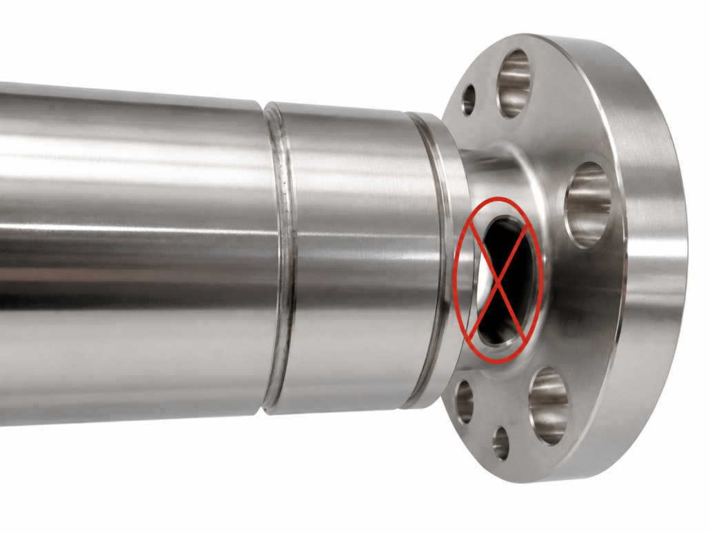
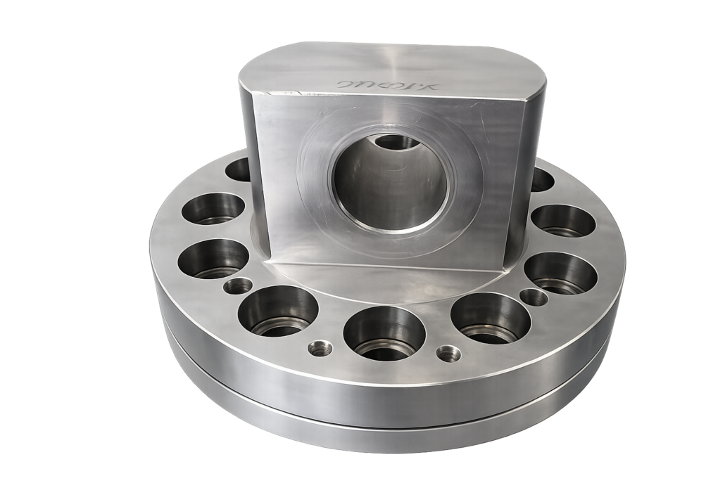
For the sensor to function correctly, it is crucial that the end faces are not locally deformed.
A local deformation is caused, for example, if a point force Fz were applied at the center of the sensor.
The force is applied across the entire surface of the circular ring between the inner centering collar and the outer diameter. The force is also applied to the trapezoidal segments of the circular ring. The recesses between the segments are not subjected to any load.
Besides the force transmission on the circular ring, the flatness and stiffness of the connecting flange are important parameters. High-strength aluminum or tempered tool steel 24CrMo4 or C60, or high-strength stainless steel 1.4542, should be used as the material. 3D-printed plastic flanges are unsuitable!
A loose screw can cause measurement errors on the order of 10% or more.
The tolerance for the flatness of the flanges is 0.02mm.
Table 1 provides guidelines for the thickness of the connection flanges and the recommended tightening torque. If the recommended tightening torque exceeds the sensor’s rated torque, no torque should be applied through the sensor. Instead, the counter-torque should be applied directly to the flange.
The screws should have a minimum strength class of 8.8. Screws with a strength class of 10.9 are recommended for torques above 100 Nm.