Cycle Testing 101
 In test and measurement, cycle testing subjects a component, subassembly, or finished product to repeated, alternating, or reciprocating loading sequences over extended durations.
While traditional fatigue testing typically concentrates on material endurance limits and structural crack propagation under cyclic stress, cycle testing encompasses a broader scope. It evaluates overall functional reliability, kinematic wear, seal integrity, switch actuation life, joint loosening, and mechanical degradation across hundreds, thousands, or millions of operating cycles.
Valid cycle testing requires sensor hardware and instrumentation that can withstand continuous dynamic oscillation without zero-balance drift, internal flexure fatigue, or signal distortion from mechanical resonance. Sensor selection, system dynamics, and mounting rigidity directly dictate measurement fidelity over extended test programs.
Cycle Testing Operational Mechanics and Dynamic Factors
In static force measurement, the applied load transfers into the load cell flexure with minimal inertial influence. In contrast, cycle testing introduces dynamic variables such as operational frequency, load-profile waveforms, and test-fixture mass that continuously affect the measurement loop.
For example, when a mechanical actuator drives an alternating profile, the load cell does not measure only the test specimen’s resistance. It also accelerates and decelerates any mechanical fixture, tooling, or adaptors positioned between the sensor’s active sensing face and the specimen. This secondary mass generates inertial forces (F = ma) that, if uncorrected, introduce phase lag and amplitude errors into the recorded force signal.
Dynamic cycle testing also requires careful evaluation of the measurement system’s natural frequency. Operating a test frame at frequencies near the load cell’s natural frequency and its fixturing causes mechanical amplification, creating measurement resonance that degrades accuracy and can rapidly overstress the sensor’s internal flexure beams. To ensure a linear signal response without dynamic distortion, a load cell’s installed natural frequency must significantly exceed the test actuator’s cyclic operating frequency.
During sustained cyclic loading, internal flexure strain produces minute localized heat through mechanical hysteresis. Furthermore, continuous strain gage bridge excitation introduces electrical heating. Sensors designed for cycle testing use specialized strain gages, temperature compensation, and matched-alloy flexures to eliminate thermal zero-shift and maintain calibration across multi-million-cycle profiles.
Sensor Types Used in Cycle Testing
Cycle testing environments demand transducers engineered specifically for high fatigue resistance and stability under alternating loads. Interface designs several sensor models that match these criteria.
LowProfile fatigue-rated load cells are machined with low internal deflection and low stress concentration factors. These shear-web pancake load cells are rated for 100 million fully reversed loading cycles in tension and compression, or compression only. Their structural geometry cancels extraneous side loads and off-center bending moments that commonly develop as test fixtures articulate or wear over time. This type of load cell includes our 1000 Fatigue-Rated Universal LowProfile® Load Cell and 1000 High Capacity Fatigue-Rated Universal LowProfile® Load Cell.
Miniature beam and S-type load cells are common for validation, endurance, and performance cycle testing across all product and component types. Their compact size makes them ideal for cycle testing in space-constrained applications. Mini load cells are compact universal load cells that capture cyclic forces across a range of capacities. Specialized alloy construction ensures durability despite their reduced size. Load cells for this type of testing include our SSMF Fatigue Rated S-Type Load Cell and MBI Overload Protected Miniature Beam Load Cell.
Reaction and rotary torque transducers are used in machines, tools, and switches for cyclic testing. Rotary torque measures components such as valves, power tools, hinges, and mechanical assembly devices. Reaction torque sensors measure reversing oscillatory torque without rotating, while shaft-style rotary transducers monitor continuous cyclical rotations under sustained dynamic loads.
Multi-axis sensors provide valuable data when an oscillating assembly experiences axial and lateral loads, such as a gripper, ball joint, or articulated simulator that requires high-cycle-count testing. Multi-axis sensors capture independent linear forces and bending moments simultaneously without requiring complex multi-sensor linkage assemblies.
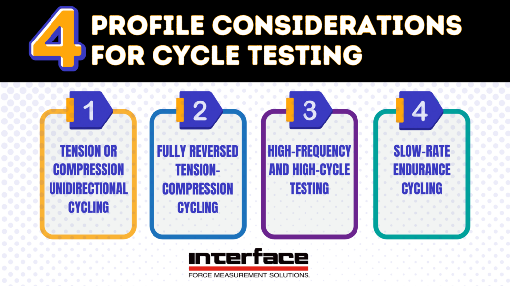
Four Test Profile Considerations for Cycle Testing
Selecting the right test architecture for cycle testing depends on the method and test-profile parameters. Here are four profile examples.
#1 – Tension-Only or Compression-Only Unidirectional Cycling
This type of cycling exerts load from zero to a predetermined peak value. Because the sensor does not transition through zero load into reverse stress, the flexure experiences half-cycle fatigue, so standard universal load cells can be used if properly derated for peak dynamic loads.
#2 – Fully Reversed Tension-Compression Cycling
This cycling profile drives the load through zero into alternating positive and negative states. This reversal shifts internal strain fields across tension and compression, requiring a dedicated fatigue-rated sensor whose mechanical design prevents micro-yielding and premature flexure failure.
#3 – High-Frequency and High-Cycle Testing
Operating at tens or hundreds of hertz requires low-mass, ultra-high-stiffness load cells. In these systems, minimal sensor deflection reduces mechanical stroke requirements on hydraulic or electrodynamic actuators, optimizing system response and maximizing actuator displacement efficiency.
#4 – High-Frequency and High-Cycle Testing
This test profile emphasizes long-term zero stability, minimal creep, and high bridge output over weeks or months of continuous cycling, prioritizing bridge balance over high natural frequency.
Installation, Alignment, and Signal Conditioning Criteria
Achieving dependable data across millions of cycles requires strict attention to mechanical crossing points and electronic data collection. As an example, watch this installation video of our S-Type Load Cells.

Maintain mechanical alignment along the measurement axis throughout the entire cycle stroke. For example, angular or parallel misalignment between the actuator, the load cell, and the specimen introduces extraneous shear forces and bending moments. Even when using fatigue-rated shear-web sensors that inherently attenuate side loads, sustained excessive off-axis vectors reduce the fatigue life of mounting studs, bearings, and flexure elements. Incorporate rod end bearings, spherical alignment couplers, or precision-machined guide bushings to decouple unintended parasitic bending moments.
Torque fasteners to precise engineering values using calibrated torque tools. In dynamic cycling environments, cyclic stress reversals can loosen joints, leading to impact fretting, signal noise, and catastrophic bolt shear. Verify thread engagement depth, high-strength alloy studs, and positive locking mechanisms before initiating long-term test cycles.
Data acquisition instrumentation must match the test’s dynamic profile. Analog signal conditioners and bridge amplifiers require adequate bandwidth to track the chosen cyclic waveform without attenuating high-frequency peaks or phase-shifting transient events. Digital sampling rates should provide at least 20 to 50 discrete data points per waveform cycle to ensure accurate peak-and-valley force tracking. For long-term cycle testing, data systems often utilize automated envelope tracking or burst logging to capture peak cyclic limits without generating excessively large data files.
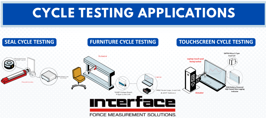
Cycle Testing Applications Using Interface Sensors and Instrumentation
Cycle testing spans multiple engineering disciplines, requiring certification of structural integrity, wear life, and functional actuation under repetitive operating conditions.
- Automotive Component and Subsystem Validation: Evaluating suspension bushings, door hinges, brake pedal assemblies, shock absorber mounts, and seat latch mechanisms under millions of simulated road-load and actuation cycles.
- Aerospace Fastener and Control Surface Cycling: Subjecting structural bolts, composite joints, flap actuators, and primary control linkages to continuous reversed-load spectrum testing to verify fatigue life before scheduled maintenance intervals.
- Robotic Cable and Joint Flex Cycling: Verifying the mechanical life of specialized cables, flex conduits, and articulated robotic joints subjected to repetitive bending and torsional oscillations on automated production lines.
- Consumer Electronics and Switch Testing: Measuring actuation force, tactile detent degradation, and spring fatigue across hundreds of thousands of cycles on pushbuttons, keypads, laptop hinges, and foldable screen assemblies.
- Packaging and Container Integrity: Evaluating seal strength, crimp durability, and cyclic pressure retention on pharmaceutical vials, beverage cans, and industrial fluid packaging.
- Industrial Valve and Actuator Endurance: Monitoring dynamic torque and seating thrust over extended open-close duty cycles to evaluate seal degradation, packing friction, and motor performance under continuous operating pressure.
- Medical Device and Implant Durability: Running orthopedic joint implants, spinal rods, surgical staplers, catheter mechanisms, and drug delivery pumps through high-cycle simulation protocols to satisfy regulatory durability standards.
Learn more in Interface’s video about high-cycle testing.
Rely on Interface for Cycle Testing
Cycle testing is a fundamental evaluation methodology used to verify product endurance, track mechanical wear, and establish operational life expectancy under repetitive dynamic loading. Unlike static force measurement, dynamic testing requires careful evaluation of operational frequency, fixture mass acceleration, structural natural frequency, and mechanical alignment to prevent signal distortion and sensor fatigue failure.
Selecting transducers engineered for high cycle counts, such as fatigue-rated LowProfile load cells, miniature sensors, multi-axis transducers, and reaction torque sensors, lets test engineers capture synchronized, highly repeatable force and torque data over extensive test cycles. Paired with high-bandwidth signal conditioning, rigid mechanical interfaces, and proper fixture isolation, these sensors deliver the measurement integrity needed to validate components across aerospace, automotive, medical, energy, and industrial testing environments.