Mastering The Signal Chain in Test and Measurement
 In test and measurement configurations that use sensors such as load cells, torque transducers, and multi-axis components, these devices represent only the first stage of the connected instrument chain. Sensor data integrity depends on the entire signal chain.
What is the signal chain in test and measurement? It is the complete, interconnected hardware and software continuum that converts a physical event into validated engineering units. It encompasses the raw strain gage bridge, regulated excitation sources, local analog conditioning, filtering, high-resolution digitization, network transmission, and the final analytical software interface.
Older test laboratories and integrators often treat instrumentation and interconnectivity as an add-on or afterthought, running long analog leads across test bays and factory floors into central data recorders. Modern testing and integration projects recognize that raw analog signals in the mV/V range can introduce vulnerabilities in different environments, such as electromagnetic interference, impedance shifts, and thermal degradation. If noise corrupts a bridge signal before digitization, no post-processing algorithm can recover the lost information.
Transforming the Test Lab to High-Speed Data Acquisition and AI Modeling
Across global industries, from aerospace and automotive to medical device design and industrial automation, test engineers are transforming how physical forces become digital insights. Rather than managing complex analog wiring looms and troubleshooting ground loops, measurement sensors and systems can deploy distributed, synchronized digitizers directly at the sensor to enhance the signal chain’s effectiveness. This architecture supports automated test benches, digital twin validation, and machine learning pipelines that use reliable, high-accuracy sensors in current connected network environments.
This direct physical-to-digital pathway provides immediate operational visibility. In aerospace structural rigs, hundreds of load channels stream synchronously into finite element validation software. In automated automotive powertrain testing, torque-angle curves are digitized fast enough to capture material yield in real time.
Furthermore, artificial intelligence frameworks and predictive mechanical models rely on clean training datasets from sensor outputs. When feeding weight, torque, or force data into neural networks for structural health monitoring or component fatigue prediction, noise spikes or drift can be misinterpreted as physical anomalies. A stable, calibrated signal chain provides deterministic data, ensuring that machine learning models train on actual material behavior rather than electrical artifacts.
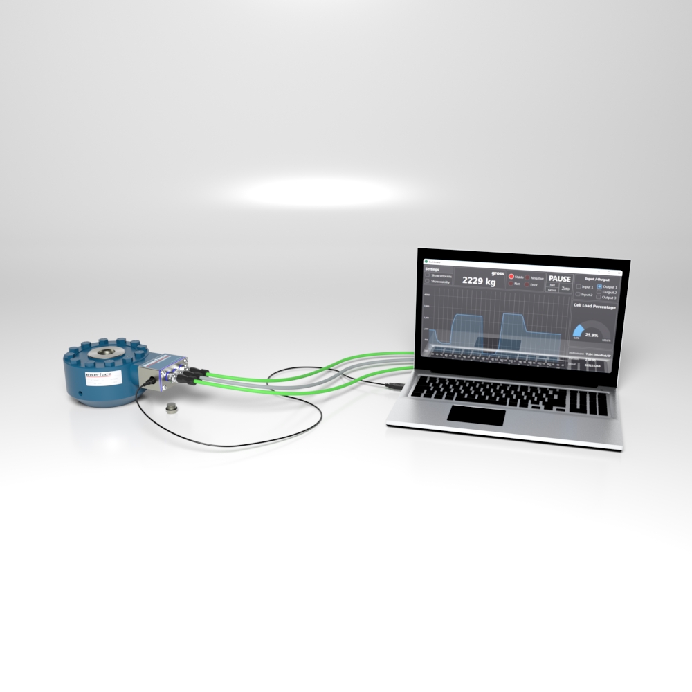
1200 LowProfile ILCB Digitizer EtherCAT Complete System
Mapping the Hardware Architecture from Sensor to Actionable Network Data
Building effective test architecture requires selecting hardware that matches the physical signal path step by step. Each component in the chain must preserve signal fidelity, eliminate noise sources, and convert raw millivolt levels into standardized data formats. Whether you deploy an ILCB In-Line Load Cell Digitizer to make the connection or use Wireless Telemetry System Receivers and Accessories connectivity, the key to preserving accurate data is working through each phase of building a solid signal chain.
Phase #1 – Bridge Excitation and Local Amplification
Compact in-line units like CSC and LCSC signal conditioners amplify low-level millivolt-per-volt outputs into filtered DC signals directly along the sensor cable before external noise can degrade the signal over long distances. For control enclosures, the DMA2 DIN rail mount conditioner provides regulated excitation, user-selectable analog outputs, and switch-selectable filtering to isolate the bridge from factory electrical interference.
Phase #2 – Point-of-Test Digitization
Inline converters such as the INF-USB3 single-channel module connect directly between a strain gage transducer and a test PC via USB. Converting bridge outputs into high-resolution digital counts at the hardware interface eliminates the need for separate signal conditioning chassis and external analog acquisition boards.
Phase #3 – Synchronous Multi-Channel Processing
For multi-axis sensors and distributed load cell arrays, the BX8 data acquisition system supplies synchronized excitation across up to eight channels. It executes real-time matrix mathematics on board to decouple crosstalk vectors before streaming digitized data over USB, CAN, or Ethernet buses.
Phase #4 – Visual Display and Field Logging
The 9330 battery-powered high-speed indicator provides high-speed sampling up to 3750 Hz with onboard SD card logging for validation in tight test envelopes where tethering to a PC is impractical. For automated machinery, the 9840 intelligent indicator delivers multi-channel digital readouts, dual-limit set points, and remote calibration verification.
Phase #5 – Automated Configuration via TEDS
Transducer Electronic Data Sheet chips compliant with IEEE 1451.4 store factory calibration, excitation requirements, and sensitivity parameters directly on the sensor, allowing digital acquisition hardware to configure scaling automatically without manual entry errors.
What End-to-End Application Architectures Represent
These complete physical-to-digital workflows represent the modern engineering paradigm of eliminating manual scaling errors, mitigating analog noise before transmission, and delivering deterministic engineering units directly to control networks. In multi-axis robotics, structural fatigue rigs, and high-speed assembly lines, the following architectures illustrate how selecting matched hardware at every stage of the signal chain protects data integrity from initial strain deflection to final computational analysis.
Wireless Structural Load and Heavy Machinery Monitoring Application
- Sensor: WTS1200 Wireless LowProfile Load Cell or WTSSHK-B Wireless Crosby Bow Load Shackle.
- Signal Path and Transmission: Direct integration of an internal 2.4 GHz direct sequence spread spectrum (DSSS) radio transmitter powered by onboard lithium batteries, eliminating physical umbilical cables across moving mechanisms, overhead cranes, or high-bay test structures.
- Instrumentation: WTS-BS-6 Wireless Telemetry Base Station connected to a centralized PC or a WTS-BS-4 Industrial USB/ASCII Gateway linked to a control network.
- Signal Processing and Output: The sensor-integrated transmitter samples the strain gage bridge locally with 24-bit resolution, applies internal calibration polynomial curves, and transmits license-free encrypted RF packets up to 800 meters. The base station receives synchronized packets from multiple wireless nodes without signal degradation, converting RF data directly into USB, RS-485, or Modbus registers for continuous structural integrity logging and automated overload alarms.
Multi-Axis Robotic End-Effector Profile Application
- Sensor: 6A55RI-6-Axis installed at the robot tool flange.
- Signal Path and Cable: 6-wire shielded multiconductor cable carrying low-level millivolt signals for all six channels directly to local acquisition.
- Instrumentation: BX8 Multi-Channel Data Acquisition System mounted next to the robotic cell.
- Signal Processing and Output: The BX8 provides regulated excitation across all internal bridge amplifiers, executes synchronous channel sampling to eliminate phase lag, and calculates the factory 6×6 crosstalk matrix in real time on board. Decoupled force and moment vectors stream via EtherCAT or CAN bus directly to the robot controller and logging PC.
Automated Fastener and Powertrain Validation Application
- Sensor: T2 Ultra Precision Rotary Torque Transducer coupled in-line with an automated fastening spindle.
- Signal Path and Cable: High-flex shielded sensor cable routed from the rotating test fixture to the electrical enclosure.
- Instrumentation: 9840 Intelligent Dual-Channel Indicator or DMA2 DIN Rail Mount Signal Conditioner.
- Signal Processing and Output: The DMA2 filters high-frequency motor-drive electrical noise, provides regulated bridge excitation, and outputs high-level, isolated analog voltage. The 9840 tracks simultaneous torque and angle channels, logs peak seating values, and transmits fast pass/fail limits to the PLC via digital outputs while streaming data over RS-232/USB to the quality analytics database.
Inline Structural Component Pull-Testing Application
- Sensor: SSMF Fatigue-Rated S-Type Load Cell or 1200 Precision LowProfile Load Cell with factory-programmed IEEE 1451.4 TEDS chip.
- Signal Path and Cable: Standard 4-conductor or 6-conductor shielded cable running directly from the test stand into the digitizer.
- Instrumentation: INF-USB3 Universal Sensor-to-USB Interface Module.
- Signal Processing and Output: The INF-USB3 powers the Wheatstone bridge, automatically reads the calibration matrix and scaling parameters from the TEDS chip on connection, and converts the analog mV/V bridge output directly into 24-bit digital packets at the connector. Clean force data streams via USB directly into test software for immediate stress-strain curve generation without an intermediate amplifier chassis.
TIP: You can also use Interface Complete Systems to build a paired system for a streamlined signal chain.

INF1 Instrumentation and 1200 LowProfile Network Integration
Engineering Best Practices for Signal Integrity
Long cable runs inevitably introduce resistance-based voltage drops that degrade excitation levels and skew calibration scaling. Implementing a six-wire bridge configuration with dedicated sense lines enables the signal conditioner to actively measure and regulate voltage at the sensor bridge rather than at the instrument terminals, preserving measurement accuracy over extended distances.
Filter selection requires balancing noise rejection with dynamic event capture. Setting hardware low-pass cutoff frequencies too low will artificially dampen and clip rapid mechanical spikes, such as peak seating torque or impact forces, while setting them too high allows 50/60 Hz line hum and motor drive EMI into the data stream. Matching filter bandwidth to the rise time of the physical event ensures high-fidelity peak capture without noise contamination.
Grounding errors remain the most common source of mysterious offset drift and 60 Hz oscillations in test rigs. Grounding cable shielding at multiple points creates ground loop currents caused by slight potential differences across factory floors. Terminating the overall shield at a single point, ideally at the instrumentation or data acquisition chassis ground, sets up an effective Faraday shield without introducing circulating ground currents.
Adapting to Modern Communication Networks and Directing Action
As test facilities migrate to Industrial Ethernet protocols such as EtherCAT, CANopen, and direct PC-based networks, the signal chain must deliver noise-immune digital packets rather than long analog voltages. A test program is only as reliable as its weakest interconnect. As testing environments integrate higher channel counts, faster sampling requirements, and automated machine learning analysis, treating instrumentation as a separate add-on introduces unacceptable uncertainty.
Review your current laboratory signal paths. First, verify that bridge excitation is regulated at the sensor. Then match filter cutoff frequencies to your dynamic mechanical events and transition from long analog wire runs to localized digitization. Standardizing matched instrumentation from the strain gage bridge through the digital bus protects your test data from corruption, minimizes setup downtime, and delivers deterministic datasets ready for rigorous engineering analysis.
Contact our application and sensor technology experts to explore the best solutions for your signal chain test plan requirements.