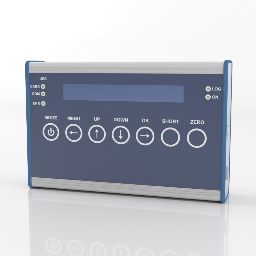
Features and Benefits
- 24-bit resolution
- 3750 Hz update rate
- Peak and valley capture
- Log to SD card at 1000Hz
- USB Port with software
- Analog Output
- Rechargeable battery
- 20 Hour battery life/300 hour standby
- Stores up to 6 sensor calibrations
- Powers up to 4x 350 ohm sensors
- 7 digit display
Amplifier channel has a fixed gain settings and is not adjustable for specific load cell output signals. Because of this, the amplifier output will typically 0.5V per mV/V of load cell output.
Specifications
Specifications
U.S. dimensions and capacities are provided for conversion only. Standard products have International System of Units (SI) capacities and dimensions.
Connector Pin Diagram
| CONNECTOR PINOUT |
| PIN | SYMBOL | FUNCTION |
| 1 | SCREEN | - |
| 2 | GNDA | GROUND ANALOG INPUT |
| 7 | TARE | ZERO-SETTING INPUT / TRIGGER INPUT |
| 9 | UE | ANALOG INPUT |
| 10 | UA | ANALOG INPUT |
| 6 | +US | + BRIDGE EXCITATION |
| 5 | -US | - BRIDGE EXCITATION (GND) |
| 8 | +UD | + SIGNAL DIFFERENTIAL INPUT |
| 15 | -UD | - SIGNAL DIFFERENTIAL INPUT |
| 13 | +UF | + EXCITATION SENSE (FOR FOUR WIRE SENSORS THE +SENSE CONNECTIONS MUST BE JUMPERED TO -EXCITATION) |
| 12 | -UF | - EXCITATION SENSE (FOR FOUR WIRE SENSORS THE -SENSE CONNECTIONS MUST BE JUMPERED TO -EXCITATION) |
| 14 | HB | HALF BRIDGE SELECTOR |
| 11 | QB120 Ohm | BRIDGE COMPLETITION RESISTOR 120 Ohm |
| 3 | QB350 Ohm | ADDITIONAL QUARTER BRIDGE 350 Ohm |
| 4 | QB1000 Ohm | ADDITIONAL QUARTER BRIDGE 1000 Ohm |
Pin 14 must be brigded with Pin 15 to connect half and quarter bridges.
Quarter bridge are connected in three-wire connection to Pin 5, Pin 8 and QB (3 and/or 11 or 4).
For more information visit Electrical Wiring Diagrams


 Vascular Clamp Force
  Rover Landing Gear
  Power Line Tension Testing

