Specifications
Specifications
International System of Units (SI) dimensions and capacities are provided for conversion only. Standard products have U.S. capacities and dimensions. SI capacities available upon special request and at an additional cost.
Dimensions
Dimensions
International System of Units (SI) dimensions and capacities are provided for conversion only. Standard products have U.S. capacities and dimensions. SI capacities available upon special request and at an additional cost.
Connector Pin Diagram
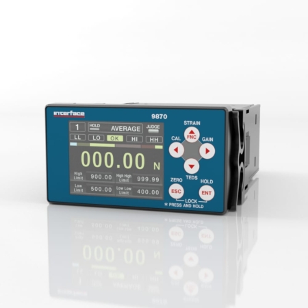
9870 Rear Panel
9870 REAR PANEL |
TERMINAL | FUNCTION | DESCRIPTION |
A | Sensor Signal Input Terminals | Terminal bank for connecting strain gauge transducers and TEDS sensors. |
B | D/A Output Terminals | |
C | Control Signal Input Terminals | |
D | Comparison Output Terminals | Connect judgment outputs. |
E | AC Adapter Jack | Connect an AC adapter. |
• Refer to the 9870 High-Speed High Performance TEDS Ready Indicator Installation & User Manual, page 24 for information about compatible plugs. DC IN 12V |
DC IN 12V |
! Do not connect both an AC adapter and a power supply to the DC power supply input terminal. |
F | DC Power Supply Input Terminals | Connect a DC power supply. The voltage range is 12–24 V DC. |
G | Frame Grounding Connector | FG connector for DC power supply. |
! Always be sure to connect the FG connector. |
Sensor Signal Input Terminals
9870 SENSOR SIGNAL INPUT TERMINALS |
TERMINAL NUMBER | FUNCTION |
1 | + SENSE/TEDS (F) |
2 | - SENSE/GND (G) |
3 | + EXCITATION (A) |
4 | - SIGNAL (B) |
5 | - EXCITATION (C) |
6 | + SIGNAL (D) |
7 | SHIELD |
- Terminals 1 and 2 are data terminals for use by both remote sense and TEDS sensors. Before connecting the sensor, set which type will be connected in advance using the Remote Sense/TEDS setting on the Calibration menu page. If “Remote Sense disabled/TEDS enabled” is selected, calibration will occur automatically if a TEDS enabled sensor is connected.
- Select “Remote Sense enabled/TEDS disabled”, if a sensor with Remote Sense is connected.
- If using a sensor with 4 wires only (No TEDS or Remote Sense), Terminals 1 and 2 can be left open.
*Note: Never combine Sense and TEDS wires in Terminals 1 and 2.
D/A Output Connectors
These can output either voltage or current. They cannot output both at the same time. Set voltage or current in System Settings D/A Converter D/A Output Mode. Refer to the 9870 High-Speed High Performance TEDS Ready Indicator Installation & User Manual, Page 73.
9870 D/A OUTPUT CONNECTORS |
TERMINAL NUMBER | SIGNAL NAME | EXPLANATION |
9 | V-OUT | D/A Voltage Output |
10 | I-OUT | D/A Current Output |
11 | COM | D/A Output Common Terminal |
- The D/A output is isolated from this unit’s circuits.
Control Signal Input Terminal
9870 CONTROL SIGNAL INPUT TERMINAL |
TERMINAL NUMBER | SIGNAL NAME | EXPLANATION |
12 | CLEAR | This turns on when a hold is cleared in any hold mode except sample hold. Set whether or not CLEAR Signals are active or inactive in Hold Function Setting → CLEAR Signal. |
13 | JUDGE | Judgment output using judgment output control signals only functions when this is ON. Set whether or not JUDGE signals are active or inactive in Comparison Setting → JUDGE Signal. |
14 | HOLD | Holds function using hold start signals when this is ON. Disable this by selecting OFF in Hold Function Setting → Hold Mode. |
15 | D/Z | Sets the indicator value digitally to 0. This is active when both System Settings → Lock → Cal. Value Lock and Condition Setting → Digital Zero → Enable Digital Zero are set to ON. |
16 | SEL1 | If System Settings Setting → Memory is set to “by signal”, the SEL1 and SEL2 terminals can be used to select the active Setting Memory. Refer to the 9870 High-Speed High Performance TEDS Ready Indicator Installation & User Manual “9-1. Setting Memory” on page 71. |
17 | SEL2 |
18 | COM | This is the control input signal common terminal. |
- The control input signal is isolated from the unit’s circuits by a photocoupler.
- Signals are input to each terminal by shorting and opening with 18 COM. A current of about 20mA results from shorting. When using a transistor, select one with a resistance of at least 10 V and elements that allow the flow of at least 40 mA when on.
- You can confirm the status of the input signal on the screen shown in “6-6. Control Input Check” on page 48 of the 9870 High-Speed High Performance TEDS Ready Indicator Installation & User Manual.
Comparison Output Connectors
9870 COMPARISON OUTPUT CONNECTORS |
TERMINAL NUMBER | SIGNAL NAME | EXPLANATION |
19 | LL | Low low limit judgment output |
20 | LO | Low limit judgment output |
21 | HH | High high limit judgment output |
22 | HI | High limit judgment output |
23 | OK | OK judgment output |
24 | COM | Comparison output common terminal |
- The comparison output is isolated from the unit’s circuits by a photocoupler. Open collector output (NPN, current sync) 20mA/30V maximum collector current
- For the operation of each signal, refer to the 9870 High-Speed High Performance TEDS Ready Indicator Installation & User Manual “7. Comparison Setting” on page 49.
For more information visit Electrical Wiring Diagrams