• Link to Facebook
  • Link to LinkedIn
  • Link to Mail
  • Link to Youtube
  • Advanced Product Search
  • Login / Register
  • My Account
  • Questions? | Email Us!
  • 480-948-5555
  • Industry Solutions
      • Industry Solutions

      • Our customers work in aerospace, automotive, energy, medical, industrial automation industries and test labs. If you are looking for inspiration or ideas, check out our solutions by industry.
      • Learn More
      • Aerospace
      • Agriculture
      • Automotive and Vehicle
      • Consumer Products
      • Education
      • Energy
      • Entertainment
      • Industrial Automation
      • Infrastructure
      • Internet of Things
      • Lifting
      • Manufacturing
      • Maritime
      • Medical and Healthcare
      • Natural Resources
      • Original Equipment Manufacturer
      • Test and Measurement
      • Weighing
  • Product Applications
      • Product Applications

      • Explore the diverse array of case studies, white papers, and application notes tailored to showcase the transformative potential of our products.
    • Applications Notes
      • Our skilled application engineers work with our customers to provide load, torque, multi-axis and force measurement solutions. Take a look at our library of Interface Application Notes.
    • Case Studies
      • Interface Case Studies are real examples of how our products are used for various applications, from packaging robots to launching rockets.
    • White Papers
      • Our technical white papers provide detailed insights, tips and expertise about various measurement technologies and use cases.
  • Products
    • Product Overview
      • Dynamic Product Categories
        • Complete SystemsComplete Systems
        • Load CellsLoad Cells
        • Mini Load CellsMini Load Cells
        • Load Button Load CellsLoad Button Load Cells
        • Multi-Axis SensorsMulti-Axis Sensors
        • Torque TransducersTorque Transducers
        • Load Pins, Tension Load Links, and Load ShacklesLoad Pins, Tension Load Links, and Load Shackles
        • InstrumentationInstrumentation
        • Digital InstrumentationDigital Instrumentation
        • WirelessWireless
        • Hazardous LocationsHazardous Locations
        • Calibration EquipmentCalibration Equipment
        • Load Cell SimulatorsLoad Cell Simulators
        • AccessoriesAccessories
        • G-SeriesG-Series
  • Product Guides
      • Interface Guides

      • Interface Guides are helpful resources to navigate our products. Our team has developed a series of instructional online tools that provide useful information about all the options available in our robust catalog.
      • Learn More
      • The Interface Selection Guide
      • Load Cell Selection Guide
      • Fundamentals of Multi-Axis Sensors
      • Multi-Axis Sensor Selection Guide
      • Mini™ Load Cell Selection Guide
      • Torque Transducer Selection Guide
      • Torque Coupling Selection Guide
      • Instrumentation Selection Guide
      • Complete Systems
      • Wireless and Bluetooth® Selection Guide
      • Cable Assemblies Guide
      • Accessories Selection Guide
      • Calibration Equipment Selection Guide
      • Load Pin Configuration Submission
      • Weighing Solutions Guide
      • Lifting Solutions Guide
      • Data AQ Pack Guide
      • BlueDAQ Software Guide
      • Caris Codes Guides
      • Interface Load Cell Field Guide
      • ForceEDU
  • Services
    • Interface Technical Services
      • 50+ years of combined experience calibrating and repairing load cells and 100,000+ calibrations performed annually.
    • ISO 17025 Scope of Accreditation
      • Interface calibration certificates are the most complete in the industry.
    • Calibration Services
      • Interface provides calibration services on load cells and other force measurement devices from nearly any manufacturer.
    • Repair Services
      • Interface provides repair services on load cells and other force measurement devices from nearly any manufacturer. Repairs include a complete evaluation of the device prior to repair and calibration upon completion.
    • Load Cell Troubleshooting
      • Performance of a load cell force (or weigh) measurement system is dependent upon the integrity of the physical installation, correct interconnection of the components, proper performance of the basic components which make up the system, and calibration of the system.
  • Custom Solutions
      • Custom Solutions

      • Interface Custom Solutions empowers you to utilize our expert engineering, design and manufacturing teams to build custom force, torque and specialty products that are customized to meet your exact needs, with precision.
      • Learn More
      • Custom OEM Solutions
      • Custom Integrated Solutions
      • System Level Calibration
  • Support
    • Locate Reps and Distributors
      • Interface’s success is due to our global network and partnership with its representatives and distributors.
    • Catalogs and Brochures
      • Interface offers downloadable PDF catalogs and brochures, including product, industry, and service guides.
    • Installation and Operation Manuals
      • Find installation and operation manuals for load cells, torque, multi-axis, load pins, links, shackles, instrumentation.
    • Software and Drivers
      • Download drivers, software and mobile apps.
    • Electrical Wiring and Diagrams
      • Electrical selection chart, load cell cable and connector wiring diagrams and more.
    • Technical Library
      • Our technical library covers cable length effects, glossaries, system calibrations, and load cell troubleshooting resources.
    • ForceEDU
      • Welcome to Interface’s ForceEdu – your go-to resource for training and professional development of Interface’s products and more. Here, you’ll find a wealth of educational materials, including training videos, 101 articles, blogs, and brochures.
  • Company
      • Company Overview

      • Founded in 1968, Interface is a U.S. based, women-owned technology and manufacturing company of the world’s best load cells, headquartered in Scottsdale, Arizona.
      • Learn More
    • Interface Capabilities
      • Interface is the world’s trusted leader in technology, design, and manufacturing of force measurement solutions. We empower engineers around the world to measure force and performance at the highest degree.
    • Trade Shows and Events
      • Throughout the year and across the globe, Interface hosts virtual ForceLeaders events, local ForceLeaders Summits, exhibits at trade shows and presents at global conferences.
    • Careers
      • Our business encompasses many different functions and capabilities, allowing you to explore careers in various fields. You can discover engineering, finance, manufacturing, marketing, product development, sales, and more opportunities.
    • Certifications and Compliance
      • Interface designs and manufactures high-performance sensors and instrumentation, ensuring ISO-compliant quality for the test and measurement market. We’re dedicated to delivering precision, reliability, and superior quality in every product.
    • InterfaceIQ Podcast
      • Listen to the InterfaceIQ Podcast, hosted by Max Newton and Molly Moment. The podcast created for new listeners, engineers, and innovators who want to learn more about force measurement technology!
  • Blog
  • Menu Menu
  • Shopping Cart Shopping Cart
    0Shopping Cart
You are here: Home1 / Blog2 / Addressing Technical FAQs in Torque Measurement

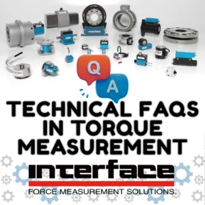
Addressing Technical FAQs in Torque Measurement
August 25, 2026/in Blog /by Jamie Glass

Torque measurement is the bedrock of performance validation in motors, drivetrains, and mechanical assemblies. While most engineers understand the fundamental relationship where torque is calculated as force applied over a perpendicular distance, implementing a torque transducer in a live test cell requires a deeper grasp of mechanical dynamics, parasitic loading, and metrological rigor.

High rotational speeds and massive transient loads demand careful integration to protect both measurement integrity and expensive instrumentation.

High rotational speeds and massive transient loads require careful integration to protect measurement integrity and expensive instrumentation. Beyond baseline formulas, successful implementation requires accounting for transient multipliers, isolating from radial and thrust loads, and selecting couplings that match the test requirements and set-up.

To select a torque transducer, engineers must first distinguish between the two primary sensor architectures: reaction versus rotary.

Reaction Torque Group 1 1

Reaction Torque Sensors: Stationary, non-rotating transducers that utilize fixed cabling to transmit signals. These are ideal for static testing or limited-rotation applications (such as valve actuation or fastener qualification), provided adequate strain relief protects the cable from fatigue. Read more in Reaction Torque 101.

Rotary Torque Group 1

Rotary Torque Sensors: Designed for continuous rotation in line with the drivetrain. Because a fixed cable would wrap around the shaft, rotary sensors use specialized transmission methods, including slip rings, rotary transformers, or wireless telemetry, to transfer data from the spinning flexure to stationary instrumentation. Get more details in Rotary Torque 101.

Beyond offering hundreds of standard and custom torque sensor configurations across diverse capacities and form factors, Interface emphasizes integration best practices that separate high-value, actionable torque data from the noise of poorly designed test stands or devices that can’t deliver the best results. If you are looking for a quick reference to navigate common and more technical torque-measurement specifications, use our Torque Transducer Cheat Sheet.

TIP:  If you are looking to explore more basic torque topics, be sure to watch our Torque 101 Webinar for valuable insights about these transducers and applications.

In this article, we explore the advanced technical aspects of using torque transducers for decision-making in test and measurement. Below are frequently asked questions, answered by our torque measurement engineers and application experts.

FAQs: Transient Loads, Capacity Selection, and Overload Protection

 #1 – What is the most common cause of torque transducer failure?

The most common cause of failure is selecting sensor capacity based solely on average running torque. In real-world drivetrains, startup surges, inertial reversals, and transient torque spikes can reach up to ten times the continuous running torque. Selecting capacity based only on steady-state operation frequently results in mechanical flexure failure. Always calculate baseline continuous torque from horsepower and rotational speed, and then apply appropriate service factor multipliers.

#2 – Why must drive and load service factors be applied as multipliers?

Operating environments vary significantly by power source and driven load. The smooth output of an electric motor or turbine is relatively benign, whereas the violent torque pulses of an internal combustion engine or reciprocating compressor generate heavy cyclic stress. Multiplying continuous torque by drive and load service factors ensures the sensor flexure operates within its fatigue rating. Additionally, installing soft starts or variable frequency drives helps control inertial startup spikes.

#3 – What is the difference between signal clipping and physical overload?

Signal clipping is an electronic limitation where peak torque exceeds the full-scale input range of the instrumentation or amplifier. The mechanical sensor is undamaged, but peak data is permanently flattened and lost. Physical overload is a mechanical event where applied torque exceeds the yield point of the sensor’s spring element flexure. This causes permanent zero-balance shifts, loss of calibration accuracy, or catastrophic mechanical fracture.

#4 – What are the trade-offs when using dual-range torque sensors?

Dual-range sensors allow engineers to capture large transient spikes on the primary range while resolving fine detail on the secondary range. However, the lower range is disproportionately sensitive to zero-point temperature drift, which can exceed the small-signal measurement error. Furthermore, because mechanical fixturing must accommodate the larger overall capacity, the assembly lacks the compact envelope of a dedicated low-capacity transducer. On lower-capacity reaction sensors, look for integrated mechanical overload stops to protect the flexure against accidental over-torque.

#5 – When should multi-axis or axial-torsion sensors be specified?

Axial-torsion sensors utilize independent Wheatstone bridge circuits on a single flexure to measure thrust loads and torsional loads simultaneously. Because both channels share a single structural element, capacities must be scaled carefully; an extreme thrust overload can mechanically distort the flexure and destroy the lower-range torsion bridge.

FAQs: Transducer Integration, Mounting, and Alignment

A torque sensor is a precision measuring instrument and must never serve as a structural load-bearing member of the driveline. Mounting geometry directly determines system longevity and measurement accuracy.

#1 – When should floating mounts be used, and what couplings do they require?

In a floating or suspended mount, the sensor is supported entirely by the drive-side and load-side shaft connections. A flexible restraining strap prevents the stationary housing from rotating while allowing compliant movement. This setup protects internal bearings from radial misalignment and must be paired with single-flex couplings at each end.

#2 – When is a pedestal (foot) mount preferred, and what couplings does it require?

Pedestal-mounted sensors bolt rigidly to a stationary machine base or subplate. This configuration is preferred for high-speed operation or test benches where test articles are frequently swapped, as the rigid base prevents drivetrain sag during component removal. Pedestal mounts require double-flex couplings on both ends to accommodate parallel and angular shaft misalignments without inducing severe bending moments across the sensor bearings.

#3 – What is the “bearing block fallacy”?

A pedestal-mounted torque sensor is not a substitute for a pillow block, jackshaft, or external support bearing. Supporting the overhung weight of heavy flywheels, pulleys, or drive motors directly on the sensor shaft will destroy the precision internal bearings and introduce parasitic crosstalk. To preserve true centerline alignment, always use precision-machined pilot bosses and external support bearings.

FAQs: Shaft Connections, Coupling and Telemetry

Couplings serve as mechanical safety valves, isolating the torque sensor from inevitable angular and parallel misalignment.

 #1 – What shaft connection provides the highest accuracy in test benches?

Smooth shafts paired with precision shrink-disc friction-style or clamping couplings are the industry standard. They eliminate backlash entirely, distribute clamping forces symmetrically around the shaft perimeter, and simplify removal without damaging precision-ground surfaces.

#2 – What is the most critical technical requirement when installing friction couplings?

Shafts and coupling bores must be clean, degreased, and completely dry. Any lubricant, anti-seize, or residue lowers the coefficient of friction, preventing the coupling from achieving its rated torque capacity and causing slippage that can score the precision shaft.

#3 – Why should keyed shafts generally be avoided in high-precision testing?

Keyed connections are susceptible to fretting corrosion and micro-backlash under alternating or cyclic torque loads. Over time, keyway wear degrades shaft integrity and corrupts high-frequency measurements. Additionally, removing keyed hubs often requires mechanical pullers or torch heat, both of which can ruin precision sensor bearings and strain gauge bonds.

#4 – Which coupling types are recommended for torque transducers?

Torsionally stiff disc-packs or bellows couplings are standard for precision measurement. They deliver high torsional stiffness for instantaneous transient response while remaining compliant enough to absorb angular and parallel misalignment. Avoid gear couplings and universal joints; gear couplings introduce backlash and axial thrust forces, while universal joints induce non-uniform velocity fluctuations and extraneous bending loads.

Torque Sensor Training Part 6 - Torque Couplings

Use the Interface Torque Coupling Selection Guide to review options and designs.

#5 – When are telemetry or battery-powered rotary systems required?

For large-diameter, uncut, or continuous driveshafts where installing an inline transducer is mechanically impractical, wireless telemetry collar systems offer a solution. Battery-powered transmitters are particularly advantageous when significant axial shaft float or variable radial gaps make inductive power transmission unreliable.

FAQs: Torque Metrology, Field Calibration, and Uncertainty

Metrological rigor ensures test data is repeatable, traceable, and defensible.

#1 – What is an overhung bending moment during calibration?

When a calibration arm is mounted directly to a sensor shaft, deadweight applied at the end of the arm induces both pure torsion and an overhung bending moment. If the transducer flexure is not designed to reject off-axis bending loads, the bending stress will crosstalk into the bridge circuit and skew the calibration curve.

#2 – Why are square-drive connections unsuitable for precision calibration?

Square-drive interfaces show loose mechanical tolerance and shifting load engagement points. As torque increases, the exact point of contact moves along the square face, altering the effective moment arm length. Flanged or precision shrink-disc connections provide the repeatable, rigid geometry required for traceable calibration standards.

#3 – How does the uncertainty budget behave across the measurement range?

Measurement uncertainty is worst-case at the lowest end of the transducer’s rated capacity. Because total calibration uncertainty is typically specified as a percentage of full-scale output, relative error grows significantly as measured values drop toward the bottom ten percent of the range.

#4 – What is the “bubble level fallacy” in calibration arm setups?

Leveling a calibration arm only at the sensor centerline ignores arm deflection under load. As calibration deadweights deflect the outer end of the arm downward, the applied gravitational force vector is no longer perpendicular to the moment arm. This introduces angular cosine error, which reduces the effective moment arm length and compromises calibration validity. High-precision calibration fixtures incorporate angle correction or leveling jacks at the load application point.

Prioritizing Torque Measurement Integrity

Rigorous torque measurement is not simply a matter of selecting a high-accuracy sensor; it requires disciplined, system-level mechanical integration. Every factor, from ensuring grease-free shrink-disc interfaces to pairing single-flex couplings with floating mounts, directly impacts measurement fidelity.

Protecting against ten-times transient peak loads, eliminating extraneous bending moments, and accounting for full-scale metrological uncertainty ensure that test data remains accurate, repeatable, and dependable.

Explore more about torque transducers and measurement integrity in our webinar, New Twist on Torque. If you have questions about torque measurement or transducer selection, please contact us for help.

New Twist on Torque Webinar

ADDITIONAL RESOURCE

Torque Measurement Primer – 2024 Edition
Tags: alignment, average running toque, axial torsion, bearing block, couplings, drive, drivetrain, dual-range torque, engineering, floating mounts, IQ Blog, IQBlog, load service, metrology, mounting, overload protection, Pedestal Mount, physical overload, reaction torque transducers, rotary torque trransducers, signal clipping, technical, Technical FAQs in Torque Measurement, telemetry, torque, torque calibration, torque capacity, torque errors, Torque FAQ, torque FAQs, torque selection, torque shaft, torque transducers, transducer integration, transient loads, types of couplings
Share this entry
  • Share on Facebook
  • Share on X
  • Share on Pinterest
  • Share on LinkedIn
  • Share on Reddit
  • Share by Mail
https://www.interfaceforce.com/wp-content/uploads/technical-FAQs-torque.png 800 800 Jamie Glass /wp-content/uploads/Interface_White_Red.svg Jamie Glass2026-08-25 08:08:522026-08-24 14:18:47Addressing Technical FAQs in Torque Measurement
You might also like
Earth from Space The AxialTQ Dynamometer
ELECTRIC VEHICLE Interface 1 1 The Next Generation of Torque Measurement Devices is AxialTQ
Teamwork 1 The Power of Teamwork Drives Interface Success
Custom Solutions 1 1 Interface Goes Above and Beyond with Custom Solutions
MULTI AXIS SENSORS 2 1 Better Data and Performance with Interface Multi-Axis Sensors
ELECTRIC VEHICLE Interface 1 1 The Future of Automotive is Electric

SUBSCRIBE TO THE INTERFACEIQ BLOG

  • Remember to subscribe to Interface’s IQ Blog. It’s a must-read for anyone looking to stay informed and up-to-date on the world of load cells with expert insights, engaging content, and a fresh perspective.

Latest Posts

  • Addressing Technical FAQs in Torque MeasurementAugust 25, 2026 - 8:08 am
  • Mastering The Signal Chain in Test and MeasurementAugust 20, 2026 - 8:08 am
  • Interface Mini Complete Systems Streamline Test and MeasurementAugust 18, 2026 - 8:08 am
  • Technical Validation of Water Safety Equipment Across Maritime ApplicationsAugust 13, 2026 - 8:08 am
  • Complex Testing 6 Axis Bx8 DAQ
    Complex Testing with 6-Axis Load Cells and BX8 DAQ InstrumentationAugust 11, 2026 - 8:08 am

Explore our Products

  • Accessories
  • Calibration Equipment
  • Digital Instrumentation
  • G-Series
  • Hazardous Locations
  • Instrumentation
  • Load Button Load Cells
  • Load Cell Simulators
  • Load Cells
  • Load Pins, Tension Load Links, and Load Shackles
  • Mini Load Cells
  • Multi-Axis Sensors
  • Quickship
  • Torque Transducers
  • Wireless

All Products

  • Load Cells
  • Interface Mini
  • Load Button Load Cells
  • Multi-Axis Sensors
  • Torque Transducers
  • Load Pins, Tension Links, and Load Shackles
  • Instrumentation
  • Digital Instrumentation
  • Wireless Telemetry System
  • Bluetooth® Telemetry System
  • Intrinsically Safe
  • Calibration Systems
  • Accessories
  • G-Series

Contact Us

  • Feedback
  • Customer Support
  • Contact Form
  • Career Opportunities
  • Certifications and Compliance
  • Locate A Rep or Distributor

Solutions

  • ForceEDU
  • Custom Solutions
  • Industry Solutions
  • Application Notes
  • Animated Application Notes
  • Case Studies
  • White Papers
  • Interface Training Videos

Services

  • Calibration and Repair Request
  • Load Cell Troubleshooting
  • Software and Drivers
  • Technical Library

News

  • Events
  • Newsletter
  • Interface IQ Blog
  • InterfaceIQ Podcast
ISO 17025 Scope Accreditation
© Copyright - Interface - powered by Enfold WordPress Theme
  • Warranty And Repair Policy
  • Privacy Policy
  • Certifications and Compliance
Link to: Space Tech Expo Europe Link to: Space Tech Expo Europe Space Tech Expo Europe
Scroll to top Scroll to top Scroll to top

We use cookies to enhance your browsing experience, serve personalized content, and analyze our traffic. By clicking "Accept All Cookies", you consent to our use of cookies.

Accept All CookiesReject AllCookie Settings

Cookie and Privacy Settings


How we use cookies

How we use cookies

We may request cookies to be set on your device. We use cookies to let us know when you visit our websites, how you interact with us, to enrich your user experience, and to customize your relationship with our website.

Click on the different category headings to find out more. You can also change some of your preferences. Note that blocking some types of cookies may impact your experience on our websites and the services we are able to offer.

Essential Website Cookies

Essential Website Cookies

These cookies are strictly necessary to provide you with services available through our website and to use some of its features.

Because these cookies are strictly necessary to deliver the website, you cannot refuse them without impacting how our site functions. You can block or delete them by changing your browser settings and force blocking all cookies on this website.

Google Analytics Cookies

Google Analytics Cookies

These cookies collect information that is used either in aggregate form to help us understand how our website is being used or how effective our marketing campaigns are, or to help us customize our website and application for you in order to enhance your experience.

If you do not want us to track your visit to our site, you can disable tracking in your browser here:

Other external services

Other external services

We also use different external services like Google Webfonts, Google Maps and external Video providers. Since these providers may collect personal data like your IP address we allow you to block them here. Please be aware that this might heavily reduce the functionality and appearance of our site. Changes will take effect once you reload the page.

Google Webfont Settings:

Google Map Settings:

Privacy Policy

Privacy Policy

I agree to the terms and conditions laid out in the Privacy Policy

Update Your SettingsDo not accept and hide notification
Open Message Bar Open Message Bar Open Message Bar

Please share your location to continue.

Check our help guide for more info.

share your location