Features and Benefits
- Outputs 4-20mA, 0-10V, 0-5V, ±10V, ±5V
- Zero and span adjustments
- 1kHz bandwidth
- CE approved (CSC)
- High noise immunity
- Great for OEM applications (LCSC)
- Reverse polarity protected
NOTE: Input: 0.5-150 mV/V input range – must be specified at time of order.
Specifications
Specifications
U.S. dimensions and capacities are provided for conversion only. Standard products have International System of Units (SI) capacities and dimensions.
Connector Pin Diagram
CSC-2, CSC-3, CSC-6 & CSC-7 Connections
The power supply for the CSC-2&3 are nominally 22 V dc (between 13 and 28 V) and CSC-6&7 are nominally 22 V dc (between 8.5 and 28 V).The power supply is common with the output at the ‘com’ connection.
Connection Details for the CSC-2, CSC-3, CSC-6 & CSC-7
The strain gauge cable should be attached to the solder pads as illustrated For most applications 3 wire un-shielded field wiring is quite adequate. For best EMC performance use the connections shown below.
Connection Details for Best EMC Immunity
The CSC should be mounted by means of the bolt hole. This capacitively couples the common of the CSC and CSC electronics to the strain elements in the load cell which improves the EMC susceptibility performance.
Take note of the grounding arrangement particularly the bolt hole which capacitively couples the common of the CSC electronics to the strain elements in the load cell which improves the EMC performance.
CSC-4, CSC-1 & CSC-5 Connections
The CSC-4 requires a ±14V bipolar dc power supply within the limits of ±13 V to ±15 V. The CSC-1 & CSC-5 require a 12 to 24 V uni-polar dc power supply. Ideally this should be limited to +15 V to +18 V for 350 Ohm load cells to minimize the on-board temperature rise thereby reducing any warm-up time. In both cases the power supply ground is common with the output ground at the ‘Com’ connection.
Connection Details for the CSC-4
The strain gauge cable should be attached to the solder pads as illustrated For most applications 3 wire un-shielded connections for field wiring is quite adequate.
For best EMC performance use the connections shown above.
Connection Details for the CSC-1 & CSC-5
The power supply connections for the CSC-1 & CSC-5 are located on the bottom PCB.
In the following connection diagrams the ‘-Supply’ connection can be ignored for models CSC-1 & CSC-5.
Connection Details for Best EMC Immunity
Refer to “Connection Details for Best EMC Immunity” above for CSC-1&5 power connections.
Take note of the grounding arrangement particularly the bolt hole which capacitively couples the common of the CSC electronics to the strain elements in the load cell which improves the EMC performance.
CSC-8, CSC-9 & CSC-0 Connections
The power supply for the CSC-8, CSC-9 & CSC-0 is 24 V dc (within the limits of 13 V to 28 V).
Connection Details for the CSC-8, CSC-9 & CSC-0 – Source Mode
Connection Details for the CSC-8, CSC-9 & CSC-0 – Sink Mode
Connection Details for Best EMC Immunity
Take note of the grounding arrangement particularly the bolt hole which capacitively couples the common of the CSC electronics to the strain elements in the load cell which improves the EMC performance. The CSC-8, -9 & -0 can be used with three wire cabling in both sink and source mode. The only difference between the two modes is whether the common end of the load is connected to the positive of the PSU (sink mode) or the negative of the PSU (source mode).
CSC-10 2-wire 4-20 mA
The power supply should be between 7.5 and 28 V
The minimum supply for the CSC 2-WIRE version is 9 V
Please note that by design, the excitation voltage provided by a 2-wire load cell amplifier decreases as the load cell’s impedance decreases resulting in a reduction in the load cell’s output. The lower signal level requires more gain to compensate leading to a degradation in performance with regard to temperature stability and noise performance.
Impedances greater than 1000 Ohms and sensitivities of 1mV/V and higher are recommended.
Connection Details CSC-10 2-wire 4-20
The strain gauge cable should be attached to the solder pads as illustrated.
N.B The voltage between either of the power supply connections and the load cell chassis should not exceed 50 V. Any leakage will be greater than 10 M Ohms.
Connection Details for Best EMC Immunity
The securing bolt should be used to provide a good electrical ground and mechanical support. This is important for optimum EMC performance.
Output Connections
The CSC 2-wire 4-20 analog output is 4 to 20 mA. The power and signal are combined in a single pair cable, simplifying installation.
N.B. Neither connection to the output load is electrically common to the load cell.
The following formula gives the suitable range of shunt resistance for low supply voltage operation.
Output Shunt Resistance Formula
CSC-10 2-wire 4-20: the shunt resistance must be less than:
((Vsupply -7.5) / 20 mA) – Rwiring
e.g. assuming 10 Ohms wiring resistance and 9 V supply:
Max shunt resistance = ((9 – 7.5) / 0.02) –10 = 65 Ohms
CSC 2-wire 4-20 ATEX: the shunt resistance must be less than:
((Vsupply -9) / 20 mA) – Rwiring
Calibration
The CSC amplifiers can be calibrated with the transducer connected provided that two calibration points can be implemented e.g. by applying known weights or forces. If this is not possible, a stable mV source or load cell simulator can be used if the precise sensitivity (mV/V) of the transducer is known.
Connection Details for Calibration
- Apply the known low calibration conditions (weight, force or mV/V). This may be zero if required, and using the ‘Z’ potentiometer, set the output to the relevant low level depending on the model e.g. 0.1 V for the CSC-2 & CSC-3, 4mA for the CSC-8, CSC-9 & CSC-0 etc.
- Apply the known high calibration conditions (ideally between 75% and full scale) and adjust the ‘S’ potentiometer to set the output to the relevant high level depending on the model e.g. 5.1 V for the CSC-6 & CSC-7 at full scale, 20 mA for the CSC-8, CSC-9 & CSC-0 etc.
- Apply the known low calibration conditions and re-adjust the Zero if required.
For more information visit Electrical Wiring Diagrams
Electrical
| Model | Output | Power Supply |
| VDC | mA Nom |
| CSC and LCSC-0 | 4-20mA Unipolar Comp + | 13 to 28 | 26 |
| CSC and LCSC-1 | ±10 V Bipolar | 14 to 18 | 30 |
| CSC and LCSC-2 | 0.1-10 V Unipolar Ten + | 13 to 28 | 22 |
| CSC and LCSC-3 | 0.1-10 V Unipolar Comp + | 13 to 28 | 22 |
| CSC and LCSC-4 | ±10V Bipolar | ±13 to ±15 | 22 |
| CSC and LCSC-5 | ±5V Bipolar | 14 to 18 | 30 |
| CSC and LCSC-6 | 0.1-5V Unipolar Ten + | 8.5 to 28 | 22 |
| CSC and LCSC-7 | 0.1-5V Unipolar Comp + | 8.5 to 28 | 22 |
| CSC and LCSC-8 | 4-20mA Bipolar Ten + | 13 to 28 | 26 |
| CSC and LCSC-9 | 4-20mA Unipolar Ten + | 13 to 28 | 26 |
| CSC and LCSC-10 | 4-20mA Unipolar Comp + (2-wire) | 7.5 to 28 | 20 |
| CSC and LCSC-11 | 4-20mA Unipolar Ten + (2-wire) | 7.5 to 28 | 20 |
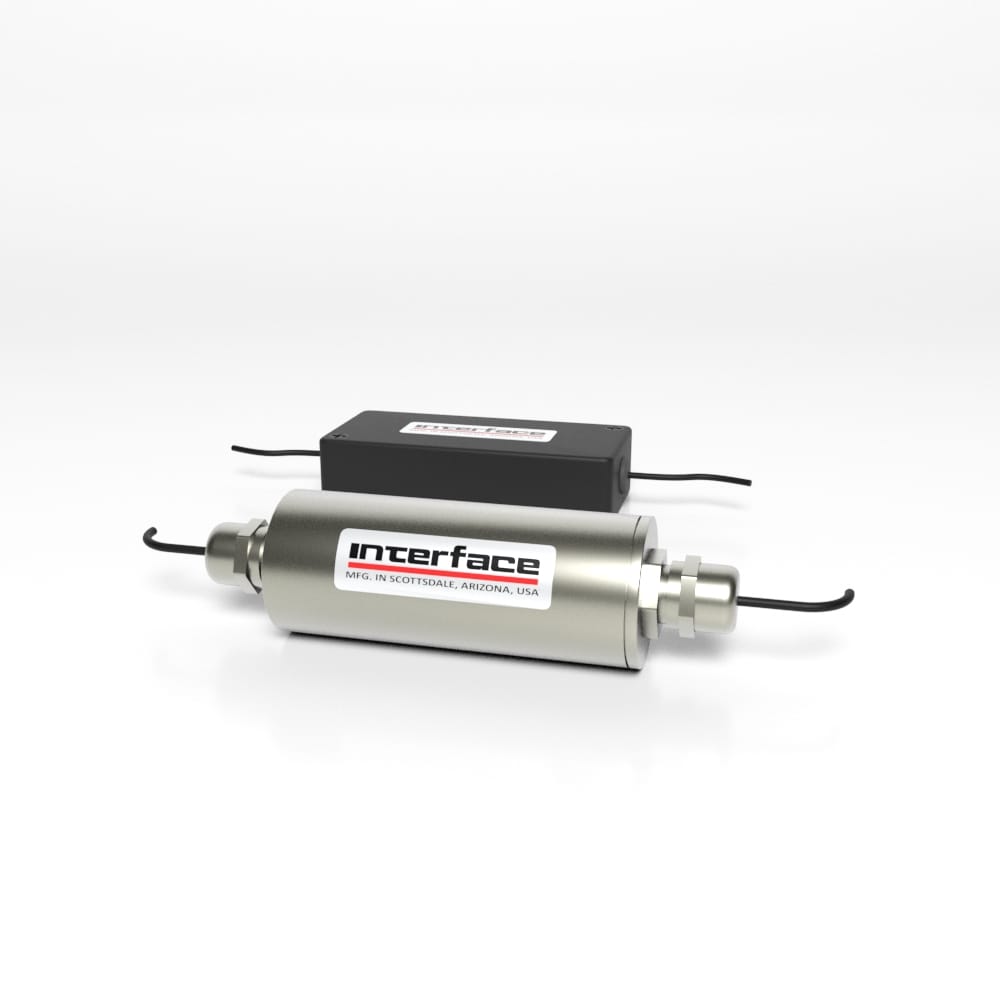
Applications Note: The Signal Conditioner models CSC and LCSC come installed and calibrated to your choice of load cell and cabling.
Reference Note: For information regarding Model CSD Embedded Load Cell Converter and Digitizer modules, see product-specific datasheet.


 Engine Dynamometer

