Features and Benefits
- Available outputs RS485, Modbus, CANbus, CANopen, and ASCII
- Linearity compensation 2 to 7-points
- 24-bit resolution (18-bit usable)
- Up to 500 samples/second
- Industrial or high stability
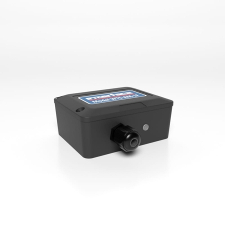
CSD Embedded Load Cell Converter and Digitizer Module
The pricing listed on our website is only for U.S. buyers and all pricing is subject to change without notice. Any inquiries for products from buyers outside of the U.S. will receive a quote and availability from the licensed distributor nearest your region. These prices will be based on product availability, currency conversions, markets, taxes, shipping costs, as well as local support.
Model CSD is an embedded load cell converter and digitizer module. Call our applications engineers for consultation to ensure the configuration meets your application needs.
Model CSD is an embedded load cell converter and digitizer module. Call our applications engineers for consultation to ensure the configuration meets your application needs.
U.S. dimensions and capacities are provided for conversion only. Standard products have International System of Units (SI) capacities and dimensions.
Refer to the CSD & DIG-D Strain gage or Load Cell Embedded Digitizer Module CANopen® – 2nd Generation User Manual, Chapter 5, for Connections to Temperature Sensor Module.
The temperature module is a connected using only two wires. The temperature sensor is the Dallas “1-Wire” digital device DS18S20. One connection is ground for which –EXC is used, and the other is the 1 wire “DQ” connection which provides the bi-directional data line.
For DIG-D the DQ connection is connected to the I/O pin marked TS.
The temperature module is a small double-sided PCB with an 8 pin SOIC integrated circuit mounted to it. The dimensions are 10.5 x 7.6 x 2.5mm. There are two solder pads for connection to the DIG-D or CSD. A 2mm hole is used for fixing the temperature module to the body of the load cell. The module should, ideally, be positioned as close as possible to the strain gages. The IC on the temperature module must also be in good thermal contact to the load cell body so the strain gages and temperature sensor see the same temperature.
Other Connections (CSD ONLY) Resistor RG and track-cut TC are used to adjust the mV/V sensitivity (see Strain Gage Sensitivity Adjustment, below).
To achieve full performance specifications and conform to environmental approvals, it is important to follow the wiring procedures outlined in this section.
The following diagram illustrates how to wire up a CSD to a strain gage
All the load cell wires should be kept as short as feasible, at most 20cm.
The EXC+/– wires should be twisted together, also the SIG+/– pair, and the two pairs kept apart. It is also recommended to secure the wires from moving due to shock or vibration. If the CSD is mounted outside the body of the load cell then, for optimal performance, twin twisted cable should be used, although standard 4 core shield cable can be used in low noise environments.
The M2 mounting hole must be grounded via an M2 screw to the load cell body for specified performance to be met. (The 2mm mounting hole to accept M2 screw or American equivalent #0-80. Important Note: DO NOT USE #2 screw size.)
The Strain Gage cable should be a twin twisted pair with independent shields, with the two pairs used for the EXC and SIG signal-pairs.
For specified performance, the load cell must be grounded to the SH.
DIG-D Sensor Cable
Require 2 × twisted-pair version, otherwise similar to the above. A suitable type is BICC Brand-Rex PD3003 (also equivalent to Belden type 8777).
In the UK, this is available from Farnell (enter ‘Belden 8777’ for real length options).
Communications Cabling and Grounding Requirements
To achieve full performance specifications and conform to environmental approvals, it is important to follow the wiring procedures outlined in this section.
CSD Power and Communications Wiring
The following diagram illustrates how to connect a puck to the communications and power supply (“bus”) cable.
CSD Bus-End Arrangement
The cable must enter the load cell via an EMC cable gland, which connects the cable shield to the load cell body. This must be a 360 Degree connection
The cable should be a twin twisted pair with independent shields, with one pair used for the communications and the other for the power wires.
There MUST be a common connection from the PSU and the CAN ground to ensure the CAN stays within the required common mode voltage of -2v (CANL) to +7v (CANH).
The shield should be connected to the grounded enclosure of the power supply.
DIG-D4 Versions- Power and Communications Wiring
The following diagram illustrates how to connect a DIG-D4 card to the communications and power supply (“bus”) cable.
DIG-D4 Versions-Bus-End Arrangement
The cable should be a twin twisted pair with independent shields, with one pair used for the communications and the other for the power wires.
The cable shield must be grounded to the SH pin at the DIG-D end, and not at the host end.
Any further metal housing should also be grounded to the DIG-D pin, and should not be connected to the bus cable shield (or the sensor cable).
There MUST be a common connection from the PSU and the CAN ground to ensure the CAN stays within the required common mode voltage of -2v (CANL) to +7v (CANH).
The Cable requirements are dependent on the bit rate of the CAN bus and the required distances. Special care is required for bit rates of over 500Kbps not only in the choice of cable used but how the bus wiring is organised i.e., the requirement for very small stub lengths for high bit rates.
For low bit rates the requirements can be specified as follows
A suitable type is BICC Brand-Rex BE56723 (also equivalent to Belden type 8723). In the UK, this is available from Farnell, part number 118-2117.
For bit rates above 500Kbps the following is recommended
Belden B3084A
Belden B8132
The ideal bus is a single length of cable, terminated at either end. Each end connects to a communicating device; while other devices are connected as near as possible directly to the main bus as it passes them (i.e., not on long side-branches).
The bus must be terminated at both ends to avoid reflections. Connecting a 120 Ohm resistor between the CANH and CANL lines does this.
It is important that the bus is loaded at each end with the corresponding line impedance, this is normally 120Ohm.
For DIG-D strain gage sensitivity adjustment please consult factory.
If your strain gage does not deliver a 2.5mV/V full scale output, you may want to adjust the sensitivity of the electronics (hardware) and/or the software gain controls.
If you want to test with an input of more than 2.5mV/V, you will have to adjust the hardware sensitivity to avoid saturating the input. If it is less, you can correct in software alone, but increasing sensitivity will generally improve accuracy.
To adjust the mV/V for DIG-D, an extra resistor ‘Rg’ is fitted across the pads RG, as shown above, in:
The link across TC can be cut to disconnect the internal 100R gain resistor: This is needed for lowering the sensitivity.
The resistor is 0805 size surface mount chip.
A 0.1%, 5ppm/Deg C resistor for the high stability version & 25ppm/ Deg C for the Industrial must be used to maintain performance.
Reducing Sensitivity
To accommodate a maximum sensor output larger than 2.5mV/V, it is necessary to reduce the electrical sensitivity of the input circuitry.
To decrease sensitivity, the link TC is cut, and the value of the resistor fitted, in Ω, should be:
Rg = (required mV/V) x 40
Example: For 10mV/V
Rg = 10 x 40 = 400Ω
Increasing Sensitivity
When the full-scale output is smaller than 2.5 mV/V, it may be desired to increase sensitivity. However, it is often possible instead to compensate partly or entirely in software, by increasing a software gain control CGAI or SGAI.
To increase sensitivity, TC is left in place, so that the fitted Rg appears in parallel (this gives better temperature stability). Its value should then be:
RG = 1 / (( 0.025 / rqd m V/V ) – 0.01)
Two effects should be noted
For more information visit Electrical Wiring Diagrams
| Dimensions | 1.25 × 2.75 × 0.65 in |
|---|
| Short Description | Sku | Price |
|---|---|---|
| Model CSD Embedded Load Cell Converter and Digitizer Module - ASCII Protocol | CSD-4-5 | $510.00 |
| Model CSD Embedded Load Cell Converter and Digitizer Module - CANopen Protocol, Industrial Stability | CSD-4C-5 | $590.00 |
| Model CSD Embedded Load Cell Converter and Digitizer Module - CANopen Protocol, High Stability | CSD-4C-R-5 | $590.00 |


 Cable Assemblies