
Torque Measurement Primer Review
 Choosing the ideal torque transducer for your project can be a daunting task. Fear not. Interface has several torque measurement tools and resources to help you navigate your options and gain confidence in the selection process.
Interface’s advanced technical Torque Measurement Primer is an excellent resource to review and save for reference. The expert guide takes you step-by-step, from torque transducer basics through complex capacity calculations to fixture and mounting considerations.
This technical reference offers considerable detail and diagrams regarding critical topics that impact the performance and accuracy of torque transducers. Interface engineer and measurement application specialist Keith Skidmore provides extensive information about defining capacity requirements, performance factors and considerations, mechanical configurations, outputs, resolution, mounting, and coupling selection tips.
Understanding Torque Transducers
A torque transducer consists of a metal spring element or flexure like a load cell. Strain gages are applied to the flexure in a Wheatstone bridge configuration. Torque applied to the sensor causes bending or shear strain in the gaged area, generating an output voltage signal proportional to torque.
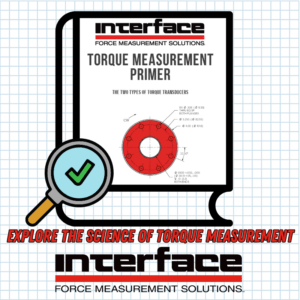
Two Main Types of Torque Transducers
- Reaction (static) measures torque without rotating, which is ideal for stationary applications.
- Rotary (dynamic) rotates as part of the system, suitable for dynamic measurements.
Normally, a reaction-style sensor has a cable attached to it to supply excitation voltage to the strain gage bridge and to output the mV/V signal. The attached cable prevents the spinning of these sensors. Various methods have been used for rotary sensors to get around the issue of the attached cable. Some of those methods include slip rings, rotary transformers, rotating electronics, rotating digital electronics, and wireless telemetry. More basics are available in our Torque Transducers 101 post.
Selecting the Right Transducer Capacity
When choosing a torque transducer, one of the primary considerations is selecting the right capacity. The key is not to overload the sensor. If you choose too large a range, the accuracy and resolution may not be enough for the application. If you choose too small a size, the sensor may be damaged due to overload, which is an expensive mistake. First, determine the amount of torque you want to measure to select the proper size. Use Interface’s Torque Transducer Selection Guide to review capacities and dimensions.
Mechanical Configurations
- Shaft: Smooth or keyed, offering uniform torque introduction and ease of assembly and disassembly.
- Flange: Shorter, with centering pilots, commonly used in limited space applications.
Reference the Torque Measurement Primer to Review Factors in the Selection
- Determine average running torque
- Understand load service factors (1-4) and drive service factors (1-4)
- What is the required accuracy
- What signal resolution do you require: analog and digital
Beyond the basics, take a deeper dive into advanced torque considerations by reviewing the following:
- Mounting methods (fixed vs. floating)
- Couplings (single and double flex)
- Environmental factors (temperature, moisture, dust)
- Variable-frequency drive applications
- Maximum RPM rating
- Bandwidth and sampling rate
Use the Interface Torque Measurement Primer to explore these factors comprehensively with technical references. It is an essential test and measurement resource for making informed torque transducer selections. Whether you are an experienced lab technician or engineer, the details of this primer are advanced and full of resourceful tips.
Request a Quote from Interface, The World Leader in Force Measurement Solutions
ADDITIONAL RESOURCES
Torque Transducers and Couplings are the Perfect Pairing
Understanding Torque Transducers for Motion Control Systems
New Interface Torque Transducer Selection Guide


