Specifying Accuracy Requirements When Selecting Load Cells
When selecting a load cell, it is important that your selection matches the type of application use case. If it is for general test and measurement requirements, a load cell model and capacity may differ from a load cell you design into a product or machine.
The first place to start in your transducer selection process of a load cell is to identify what you want to measure and your tolerance in accuracy.
Other questions will define the type of load cell, capacity, and measured specs. Do you want to measure tension, compression only, tension and compression, torque, or something else like pressure? What are your cycle counts for testing? What is the amount of measurement range you require? How controlled will the force be, both in orientation and magnitude consistency?
Once you identify early characteristic requirements for how you use the sensor, it is easier to begin evaluating options to optimize measurement accuracy.
Several aspects impact the accuracy of a load cell measurement, including:
- Sensor Specifications
- Mounting configuration
- Calibration type
- Instrumentation
- Cables
- Uncertainty of calibration
Every load cell should have a detailed specification datasheet that outlines key performance factors by model and size.
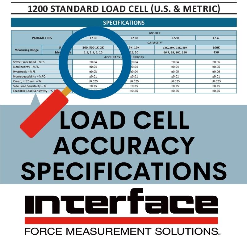
This post begins in defining specifications for accuracy as outlined for every Interface manufactured load cell. These accuracy-related specifications include:
- Static Error Band %FS – The band of maximum deviations of the ascending and descending calibration points from a best fit line through zero output. It includes the effects of nonlinearity, hysteresis, and non-return to minimum load.
- Nonlinearity %FS – The algebraic difference between output at a specific load and the corresponding point on the straight line drawn between minimum load and maximum load.
- Hysteresis %FS – The algebraic difference between output at a given load descending from maximum load and output at the same load ascending from minimum load.
- Nonrepeatability %RO – The band of maximum deviations of the ascending and descending calibration points from a best fit line through zero output. It includes the effects of nonlinearity, hysteresis, and non-return to minimum load.
- Creep % – The change in load cell signal occurring with time while under load and with all environmental conditions and other variables remaining constant. Expressed as % applied load over specific time interval.
- Eccentric Load Sensitivity: ECCENTRIC LOAD – Any load applied parallel to but not concentric with the primary axis. Results in moment load. SIDE LOAD – Any load at the point of axial load application at 90° to the primary axis.
Interface load cells are designed for precision, quality, and accuracy. Though the ranges may differ in specifications slightly, most of the performance data will far exceed industry standards. As we always say, Interface is the standard for load cell accuracy.
We will be outlining additional impacts on accuracy in upcoming posts. If you have questions on any product and specifications, as to whether it is the right load cell for your use case, contact us for help.
Additional Resources
Contributing Factors To Load Cell Accuracy
Accuracy Matters for Weighing and Scales
Interface Ensures Premium Accuracy and Reliability for Medical Applications
Interface Accelerates Accuracy in Test and Measurement
Interface Presents Load Cell Basics


