Features and Benefits
- 0-20 mA, 4-20 mA, 0-5 V, 1-5 V, and ±10 V Inputs
- 0.03% Accuracy
- Peak and valley monitoring
- 24-bit resolution
- USB Port with programming and viewing software
- Large Dual-Line 6-Digit Display, 0.60″ and 0.46″
- 32-point linearization

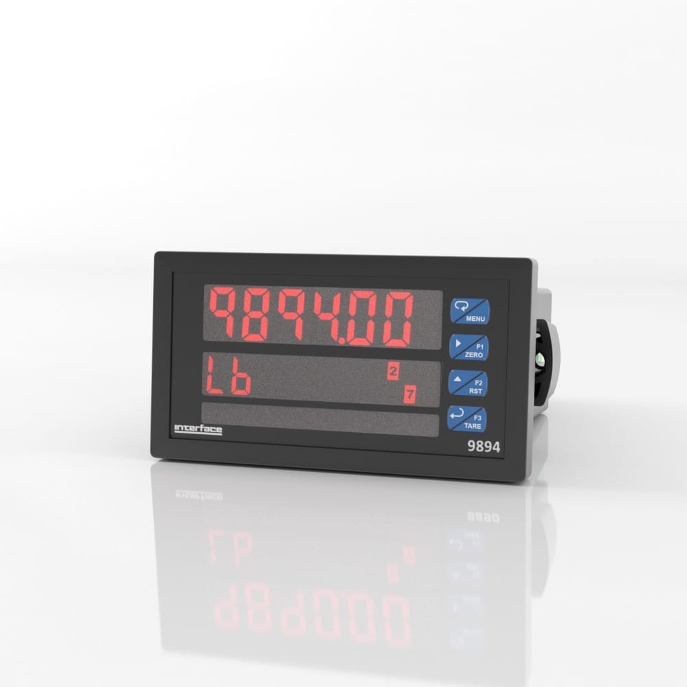
9894 Analog Input Process Indicator
The pricing listed on our website is only for U.S. buyers and all pricing is subject to change without notice. Any inquiries for products from buyers outside of the U.S. will receive a quote and availability from the licensed distributor nearest your region. These prices will be based on product availability, currency conversions, markets, taxes, shipping costs, as well as local support.
Model 9894 meter boasts specifications and functionality that clearly make it one of the most advanced process meters available. Its dual-line 6-digit display (999,999, advanced signal input conditioning, function keys, Modbus RTU serial communications, and optional expansion modules are only a few of the features found on the 9894).
Model 9894 meter boasts specifications and functionality, making it one of the most advanced process meters available. Its dual-line 6-digit display (999,999), advanced signal input conditioning, function keys, Modbus RTU serial communications, and optional expansion modules are only some features found on the 9894.
International System of Units (SI) dimensions and capacities are provided for conversion only. Standard products have U.S. capacities and dimensions. SI capacities available upon special request and at an additional cost.
International System of Units (SI) dimensions and capacities are provided for conversion only. Standard products have U.S. capacities and dimensions. SI capacities available upon special request and at an additional cost.
All meters, including models equipped with the 12-24 VDC power option, are shipped from the factory configured to provide 24 VDC power for the transmitter or sensor. If the transmitter requires 5 or 10 VDC excitation, the internal jumper J4 must be configured accordingly.
To access the voltage selection jumper:
Transmitter Supply Voltage Selection
All connections are made to removable screw terminal connectors located at the rear of the meter.
Caution! Use copper wire with 60°C or 60/75°C insulation for all line voltage connections. Observe all safety regulations. Electrical wiring should be performed in accordance with all applicable national, state, and local codes to prevent damage to the meter and ensure personnel safety.
The connectors’ label, affixed to the meter, shows the location of all connectors available with requested configuration. Note: ## on the following figures refers to power and display options. (Example: 9894-121-1)
9894 – #00 – # Connectors Label
9894 – #20 – # Connectors Label
9894 – #01 – # Connectors Label
9894 – #40 – # Connectors Label
9894 – #21 – # Connectors Label
9894 – #41 – # Connectors Label
Warning! DO NOT connect any equipment other than Precision Digital’s expansion modules, cables, or meters to the RJ45 M LINK connector. Otherwise damage will occur to the equipment and the meter.
Power connections are made to a two-terminal connector labeled POWER. The meter will operate regardless of DC polarity connection. The + and – symbols are only a suggested wiring convention.
Power Connections
Signal connections are made to a six-terminal connector labeled SIGNAL. The COM (common) terminal is the return for the 4-20 mA and the 10 V input signals.
The following figures show examples of current connections. There are no switches or jumpers to set up for current inputs. Setup and programming is performed through the front panel buttons.
Transmitters Powered by Internal Supply
Transmitter Powered by External Supply or Self-Powered
The current input is protected against current overload by a resettable fuse. The display may or may not show a fault condition depending on the nature of the overload. The fuse limits the current to a safe level when it detects a fault condition, and automatically resets itself when the fault condition is removed.
The following figures show examples of voltage connections. There are no switches or jumpers to set up for voltage inputs. Setup and programming is performed through the front panel buttons.
Voltage Input Connections
The meter is capable of accepting any voltage from 10 VDC to +10 VDC.
Serial communications connection is made to an RJ45 connector labeled M-LINK. For interfacing to the 9894, use the 989X-232 for RS-232 or the 989X-485 for RS-485. The same port is used for interfacing with all expansion modules (e.g. external relays, digital I/O).
Relay connections are made to two six-terminal connectors labeled RELAY1 – RELAY4. Each relay’s C terminal is common only to the normally open (NO) and normally closed (NC) contacts of the corresponding relay. The relays’ C terminals should not be confused with the COM (common) terminal of the INPUT SIGNAL connector.
Relay Connections
The use of snubbers to suppress electrical noise is strongly recommended when switching inductive loads to prevent disrupting the microprocessor’s operation. The snubbers also prolong the life of the relay contacts. Suppression can be obtained with resistor-capacitor (RC) networks assembled by the user or purchased as complete assemblies. Refer to the following circuits for RC network assembly and installation:
AC and DC Loads Protection
Choose R and C as follows:
R: 0.5 to 1 Ω for each volt across the contacts
C: 0.5 to 1 µF for each amp through closed contacts
Notes:
Low Voltage DC Loads Protection
RC networks are available from Precision Digital and should be applied to each relay contact switching an inductive load. Part number: 989X-6901.
Note: Relays are de-rated to 1/14th HP (50 watts) with an inductive load.
A digital input, F4, is standard on the meter. This digital input should be connected with a normally open contact across F4 and COM, or with an active low signal applied to F4. It can be used for remote operation of front-panel buttons, to acknowledge/reset relays, or to reset max/min values. A digital input, F4, is standard on the meter. This digital input should be connected with a normally open contact across F4 and COM, or with an active low signal applied to F4. It can be used for remote operation of front-panel buttons, to acknowledge/reset relays, or to reset max/min values. Refer to the 9894 Analog Input Process Indicator Installation & User Manual Function Keys & Digital I/O Available Settings on page 34 for a complete list of capabilities..
F4 Digital Input Connections
Connections for the 4-20 mA transmitter output are made to the connector terminals labeled mA OUT. The 4-20 mA output may be powered internally or from an external power supply.
4-20 mA Output Connections
The internal 24 VDC power supply powering the analog output may be used to power other devices, if the analog output is not used. The I+ terminal is the +24 V and the R terminal is the return.
Analog Output Supply Powering Other Devices
The relay and the digital I/O expansion modules 989X-4RXM & 989X-4DIOXM are connected to the meter using a CAT5 cable provided with each module. The two RJ45 connectors on the expansion modules are identical and interchangeable; they are used to connect additional modules to the system.
Note: The jumper located between the RJ45 connectors of the 989X-4DIOXM must be removed on the second digital I/O module in order for the system to recognize it as module #2.
Warning! DO NOT connect or disconnect the expansion modules with the power on! More detailed instructions are provided with each optional expansion module.
Expansion Module & DIN Rail Mounting Kit
External Relays Module Connections
Digital I/O Module Connections
As the name implies, the interlock relay feature reassigns one, or more, alarm/control relays for use as interlock relay(s). Interlock contact(s) are wired to digital input(s) and activate the interlock relay. This feature is enabled by configuring the relay, and the corresponding digital input(s), Refer to the 9894 Analog Input Process Indicator Installation & User Manual Setting Up the Interlock Relay (Force On) Feature on page 27. In the example below, an Interlock Contact switch is connected to a digital input, which will be used to force on (energize) the Interlock Relay. The Interlock Relay and the Control Relay are connected in series with the load.
Interlock Connections
For more information visit Electrical Wiring Diagrams
| Dimensions | 5.63 × 4.68 × 2.45 in |
|---|
International System of Units (SI) dimensions and capacities are provided for conversion only. Standard products have U.S. capacities and dimensions. SI capacities available upon special request and at an additional cost.
International System of Units (SI) dimensions and capacities are provided for conversion only. Standard products have U.S. capacities and dimensions. SI capacities available upon special request and at an additional cost.
All meters, including models equipped with the 12-24 VDC power option, are shipped from the factory configured to provide 24 VDC power for the transmitter or sensor. If the transmitter requires 5 or 10 VDC excitation, the internal jumper J4 must be configured accordingly.
To access the voltage selection jumper:
Transmitter Supply Voltage Selection
All connections are made to removable screw terminal connectors located at the rear of the meter.
Caution! Use copper wire with 60°C or 60/75°C insulation for all line voltage connections. Observe all safety regulations. Electrical wiring should be performed in accordance with all applicable national, state, and local codes to prevent damage to the meter and ensure personnel safety.
The connectors’ label, affixed to the meter, shows the location of all connectors available with requested configuration. Note: ## on the following figures refers to power and display options. (Example: 9894-121-1)
9894 – #00 – # Connectors Label
9894 – #20 – # Connectors Label
9894 – #01 – # Connectors Label
9894 – #40 – # Connectors Label
9894 – #21 – # Connectors Label
9894 – #41 – # Connectors Label
Warning! DO NOT connect any equipment other than Precision Digital’s expansion modules, cables, or meters to the RJ45 M LINK connector. Otherwise damage will occur to the equipment and the meter.
Power connections are made to a two-terminal connector labeled POWER. The meter will operate regardless of DC polarity connection. The + and – symbols are only a suggested wiring convention.
Power Connections
Signal connections are made to a six-terminal connector labeled SIGNAL. The COM (common) terminal is the return for the 4-20 mA and the 10 V input signals.
The following figures show examples of current connections. There are no switches or jumpers to set up for current inputs. Setup and programming is performed through the front panel buttons.
Transmitters Powered by Internal Supply
Transmitter Powered by External Supply or Self-Powered
The current input is protected against current overload by a resettable fuse. The display may or may not show a fault condition depending on the nature of the overload. The fuse limits the current to a safe level when it detects a fault condition, and automatically resets itself when the fault condition is removed.
The following figures show examples of voltage connections. There are no switches or jumpers to set up for voltage inputs. Setup and programming is performed through the front panel buttons.
Voltage Input Connections
The meter is capable of accepting any voltage from 10 VDC to +10 VDC.
Serial communications connection is made to an RJ45 connector labeled M-LINK. For interfacing to the 9894, use the 989X-232 for RS-232 or the 989X-485 for RS-485. The same port is used for interfacing with all expansion modules (e.g. external relays, digital I/O).
Relay connections are made to two six-terminal connectors labeled RELAY1 – RELAY4. Each relay’s C terminal is common only to the normally open (NO) and normally closed (NC) contacts of the corresponding relay. The relays’ C terminals should not be confused with the COM (common) terminal of the INPUT SIGNAL connector.
Relay Connections
The use of snubbers to suppress electrical noise is strongly recommended when switching inductive loads to prevent disrupting the microprocessor’s operation. The snubbers also prolong the life of the relay contacts. Suppression can be obtained with resistor-capacitor (RC) networks assembled by the user or purchased as complete assemblies. Refer to the following circuits for RC network assembly and installation:
AC and DC Loads Protection
Choose R and C as follows:
R: 0.5 to 1 Ω for each volt across the contacts
C: 0.5 to 1 µF for each amp through closed contacts
Notes:
Low Voltage DC Loads Protection
RC networks are available from Precision Digital and should be applied to each relay contact switching an inductive load. Part number: 989X-6901.
Note: Relays are de-rated to 1/14th HP (50 watts) with an inductive load.
A digital input, F4, is standard on the meter. This digital input should be connected with a normally open contact across F4 and COM, or with an active low signal applied to F4. It can be used for remote operation of front-panel buttons, to acknowledge/reset relays, or to reset max/min values. A digital input, F4, is standard on the meter. This digital input should be connected with a normally open contact across F4 and COM, or with an active low signal applied to F4. It can be used for remote operation of front-panel buttons, to acknowledge/reset relays, or to reset max/min values. Refer to the 9894 Analog Input Process Indicator Installation & User Manual Function Keys & Digital I/O Available Settings on page 34 for a complete list of capabilities..
F4 Digital Input Connections
Connections for the 4-20 mA transmitter output are made to the connector terminals labeled mA OUT. The 4-20 mA output may be powered internally or from an external power supply.
4-20 mA Output Connections
The internal 24 VDC power supply powering the analog output may be used to power other devices, if the analog output is not used. The I+ terminal is the +24 V and the R terminal is the return.
Analog Output Supply Powering Other Devices
The relay and the digital I/O expansion modules 989X-4RXM & 989X-4DIOXM are connected to the meter using a CAT5 cable provided with each module. The two RJ45 connectors on the expansion modules are identical and interchangeable; they are used to connect additional modules to the system.
Note: The jumper located between the RJ45 connectors of the 989X-4DIOXM must be removed on the second digital I/O module in order for the system to recognize it as module #2.
Warning! DO NOT connect or disconnect the expansion modules with the power on! More detailed instructions are provided with each optional expansion module.
Expansion Module & DIN Rail Mounting Kit
External Relays Module Connections
Digital I/O Module Connections
As the name implies, the interlock relay feature reassigns one, or more, alarm/control relays for use as interlock relay(s). Interlock contact(s) are wired to digital input(s) and activate the interlock relay. This feature is enabled by configuring the relay, and the corresponding digital input(s), Refer to the 9894 Analog Input Process Indicator Installation & User Manual Setting Up the Interlock Relay (Force On) Feature on page 27. In the example below, an Interlock Contact switch is connected to a digital input, which will be used to force on (energize) the Interlock Relay. The Interlock Relay and the Control Relay are connected in series with the load.
Interlock Connections
For more information visit Electrical Wiring Diagrams
| Dimensions | 5.63 × 4.68 × 2.45 in |
|---|
| Short Description | Sku | Price |
|---|---|---|
| Model 9894 Analog Input Process Indicator, AC Power | 9894-000-1 | $ 580 |
| Model 9894 Analog Input Process Indicator, DC Power | 9894-000-3 | $ 680 |
| Model 9894 Analog Input Process Indicator, AC Power, 4-20mA Output | 9894-001-1 | $ 680 |
| Model 9894 Analog Input Process Indicator, DC Power, 4-20mA Output | 9894-001-3 | $ 775 |
| Model 9894 Analog Input Process Indicator, AC Power, 4-20mA Output, 4-Relays | 9894-041-1 | $ 805 |
| Model 9894 Analog Input Process Indicator, DC Power, 4-20mA Output, 4-Relays | 9894-041-3 | $ 935 |


 5200XYZ 3-Axis Force Moment Load Cell