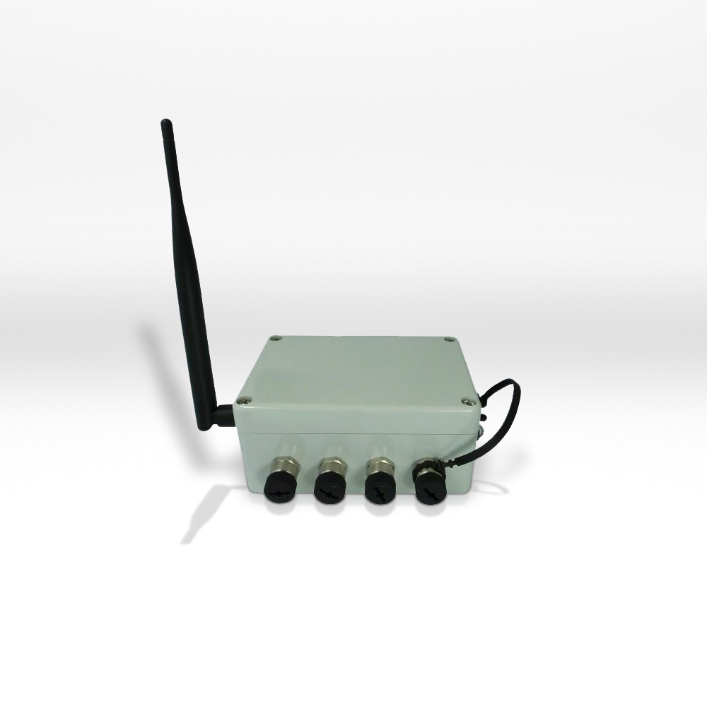
Specifications
Specifications
U.S. dimensions and capacities are provided for conversion only. Standard products have International System of Units (SI) capacities and dimensions.
Dimensions
Dimensions
U.S. dimensions and capacities are provided for conversion only. Standard products have International System of Units (SI) capacities and dimensions.
Connector Pin Diagram
Wiring Diagram
Note: The antenna may not be shielded by conductive materials or liquids. The status LED indicates whether a Bluetooth connection exists.
Strain Gage Full Bridge
FUNCTION |
CHANNEL 1 |
CHANNEL 2 |
CHANNEL 3 |
CHANNEL 4 |
+Us |
2 |
13 |
24 |
35 |
+Ud |
3 |
14 |
25 |
36 |
-Ud |
4 |
15 |
26 |
37 |
+Ud |
5 |
16 |
27 |
38 |
SW. |
1 |
12 |
23 |
34 |
Strain Gage Half Bridge
FUNCTION |
CHANNEL 1 |
CHANNEL 2 |
CHANNEL 3 |
CHANNEL 4 |
+Us |
2 |
13 |
24 |
35 |
+Ud |
3 |
14 |
25 |
36 |
-Us |
5 |
16 |
27 |
38 |
HBx |
8 |
19 |
30 |
41 |
SW. |
1 |
12 |
23 |
34 |
The active Strain Gage R3 and R4 are connected to the terminals +Us, +Ud, and -Us.
HBx: The solder bridges “8”, “19”, “30” or “41” must be closed so that the internal extension resistors R1 and R2 are activated.
Strain Gage Quarter Bridge
FUNCTION |
CHANNEL 1 |
CHANNEL 2 |
CHANNEL 3 |
CHANNEL 4 |
+Ud |
3 |
14 |
25 |
36 |
-Us |
5 |
16 |
27 |
38 |
HBx |
8 |
19 |
30 |
41 |
AUX |
6 |
17 |
28 |
39 |
QB 120 |
11 |
22 |
33 |
44 |
QB 350 |
10 |
21 |
32 |
43 |
QB 1000 |
9 |
20 |
31 |
42 |
SW. |
1 |
12 |
23 |
34 |
The active Strain Gage R4 is connected to the terminals +Ud, AUX and -Us in 3-wire technology.
HBx: The solder bridges “8”, “19”, “30” or “41” must be closed so that the internal extension resistors R1 and R2 are activated.
A solder bridge should be set depending on the Strain Gage resistance (120/350/1000 Ohm), e.g. 120 Ohm at channel 1: Solder bridge 11 (vertical); 350 Ohm at channel 2: Solder bridge 21 (horizontal).
PT-1000
FUNCTION |
CHANNEL 1 |
CHANNEL 2 |
CHANNEL 3 |
CHANNEL 4 |
AUX |
6 |
17 |
28 |
39 |
|
7 |
18 |
29 |
40 |
-Us |
5 |
16 |
27 |
38 |
QB 1000 |
9 |
20 |
31 |
42 |
HBx |
8 |
19 |
30 |
41 |
SW. |
1 |
12 |
23 |
34 |
HBx: The solder bridges “8”, “19”, “30” or “41” must be closed so that the internal extension resistors R1 and R2 are activated.
The solder bridges “9”, “20”, “31” or “42” (horizontal) must be closed.
Thermocouple Cable Type K
FUNCTION |
CHANNEL 1 |
CHANNEL 2 |
CHANNEL 3 |
CHANNEL 4 |
+Ud |
3 |
14 |
25 |
36 |
-Ud |
4 |
15 |
26 |
37 |
-Us |
5 |
- |
- |
- |
QB 1000 |
9 |
- |
- |
- |
|
7 |
- |
- |
- |
HBx |
8 |
19 |
30 |
41 |
SW. |
1 |
12 |
23 |
34 |
AUX |
6 |
17 |
28 |
39 |
c
A reference sensor PT1000 must be connected to channel 1, Ue “0-5 V” terminal, AUX and -Us.
The thermocouple cable is connected to terminals +Ud and -Ud.
Voltage Input 0-5 V
FUNCTION |
CHANNEL 1 |
CHANNEL 2 |
CHANNEL 3 |
CHANNEL 4 |
Ue 0-5V |
7 |
18 |
29 |
40 |
-Us |
5 |
16 |
27 |
38 |
SW. |
1 |
12 |
23 |
34 |
Voltage Input 0-10 V
FUNCTION |
CHANNEL 1 |
CHANNEL 2 |
CHANNEL 3 |
CHANNEL 4 |
Ue 0-5V |
7 |
18 |
29 |
40 |
-Us |
5 |
16 |
27 |
38 |
SW. |
1 |
12 |
23 |
34 |
Switch Configuration BSC4D-BT M12
INPUT |
1 |
2 |
3 |
4 |
5 |
6 |
7 |
8 |
BROWN |
RED |
ORANGE |
YELLOW |
GREEN |
BLUE |
PURPLE |
GRAY |
STAIN GAGE |
OFF |
OFF |
OFF |
OFF |
OFF |
ON |
ON |
OFF |
PT1000 |
ON |
OFF |
OFF |
OFF |
OFF |
OFF |
OFF |
ON |
VOLTAGE |
OFF |
OFF |
OFF |
ON |
OFF |
OFF |
OFF |
OFF |
THERMO CABLE + ON CHANNEL 1 - PT1000 |
OFF |
OFF |
OFF |
OFF |
ON |
ON |
ON |
OFF |
ON |
OFF |
OFF |
ON |
OFF |
OFF |
OFF |
OFF |
HALF BRIDGE |
OFF |
OFF |
OFF |
OFF |
ON |
OFF |
ON |
OFF |
QUARTER BRIDGE 1000 Ohm |
ON |
OFF |
OFF |
OFF |
ON |
OFF |
ON |
OFF |
QUARTER BRIDGE 120 Ohm |
OFF |
ON |
OFF |
OFF |
ON |
OFF |
ON |
OFF |
QUARTER BRIDGE 350 Ohm |
OFF |
OFF |
ON |
OFF |
ON |
OFF |
ON |
OFF |
DISPLACEMENT SENSOR |
OFF |
OFF |
OFF |
ON |
OFF |
OFF |
OFF |
OFF |
Pin Configuration for External Supply Voltage M8 4-Pole
The external supply voltage can be connected via 4-pole round plug connector M8.
PIN |
FUNCTION |
M8 CABLE |
1 |
SUPPLY VOLTAGE 9-28 VDC |
BROWN |
2 |
BATTERY 4.2V |
WHITE |
3 |
GND SUPPLY VOLTAGE |
BLUE |
4 |
BATTERY GND |
BLACK |
Pin Configuration BSC4D-BT M12
5-PIN PORT M12X1, TYPE 763 |
FUNCTION |
DESCRIPTION |
PIN |
COLOR |
-Us |
- SENSOR SUPPLY |
2 |
WHITE |
+Us |
+ SENSOR SUPPLY |
1 |
BROWN |
+Ud |
+ DIFFERENTIAL INPUT |
3 |
BLUE |
-Ud |
- DIFFERENTIAL INPUT |
4 |
BLACK |
AUX |
AUX IN INPUT WITHOUT CABLE |
5 |
GRAY |
Connection Plan for BSC4D-BT M12
For more information visit Electrical Wiring Diagrams