Customer would like to know how a prosthetic foot responds as it is loaded during different stances.
Interface Solution
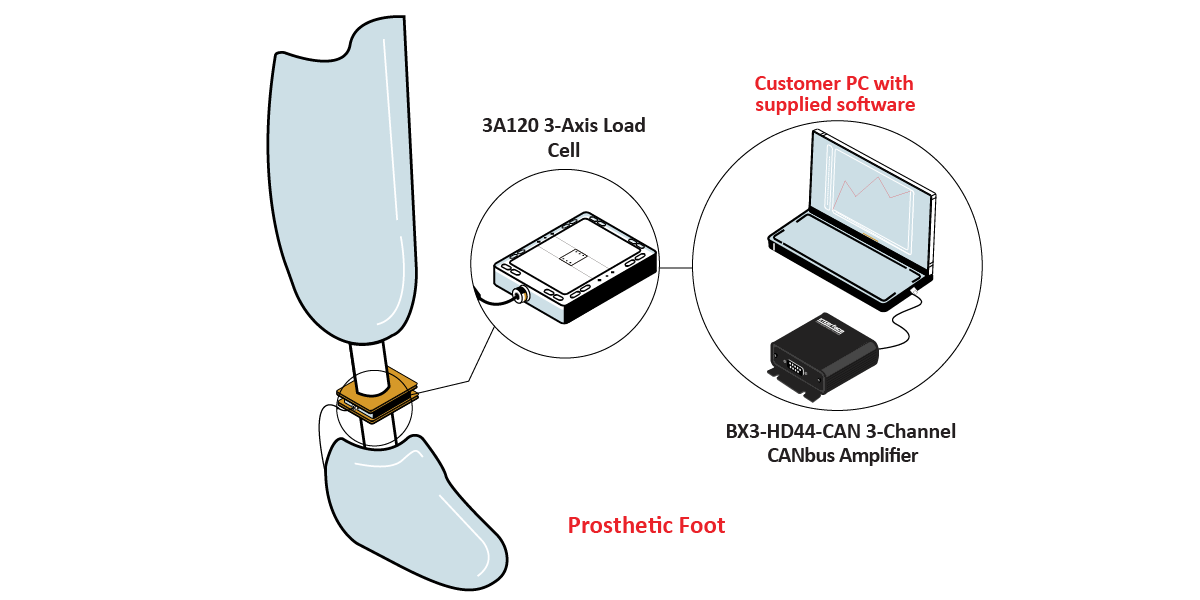
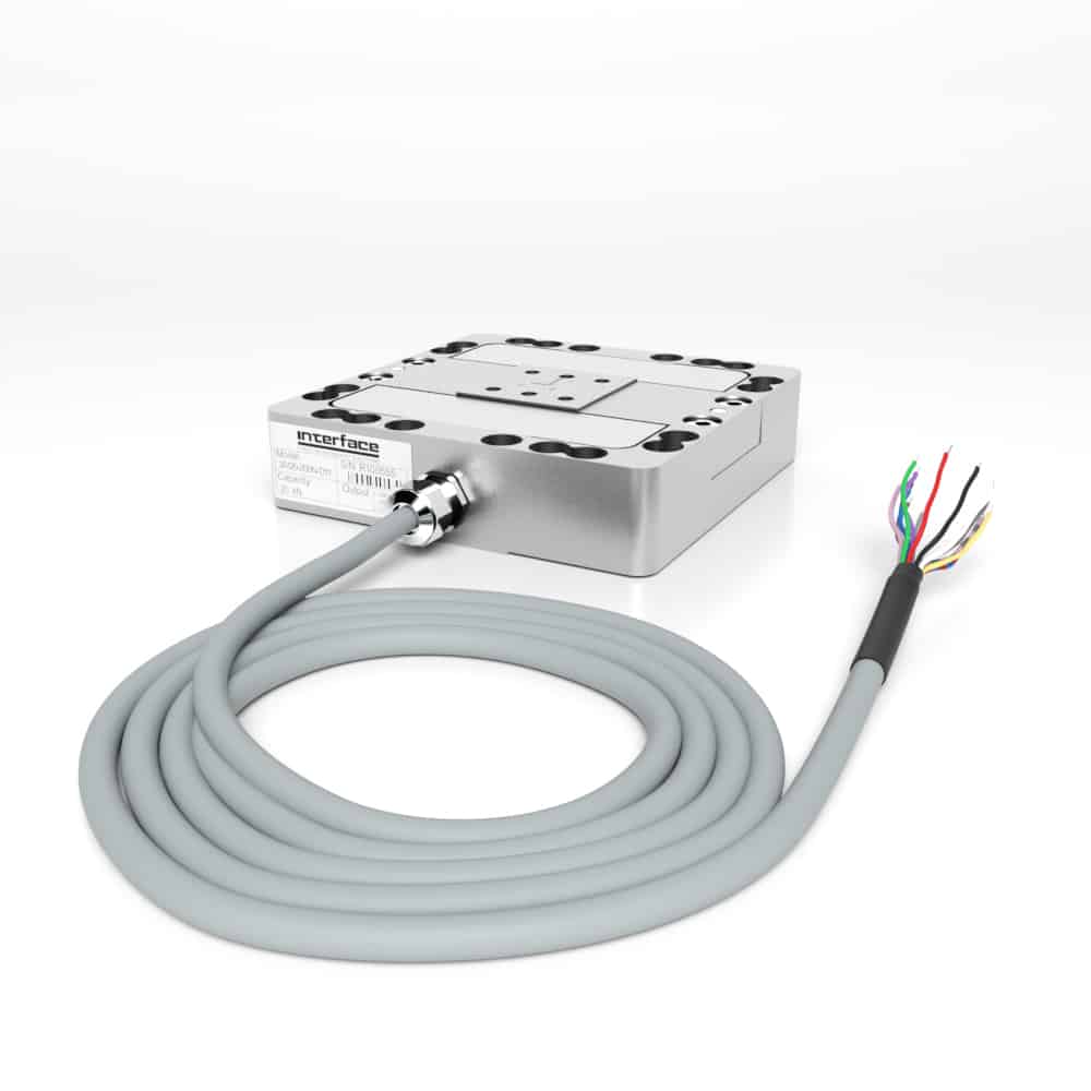
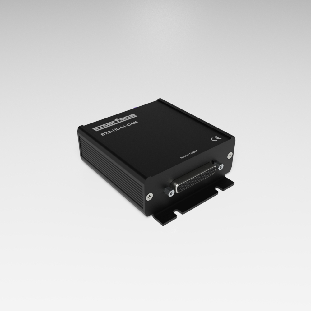
Interface’s 3A120 3-Axis Load Cell was installed between the leg socket and the prosthetic foot. The 3A120 was then connected to the BX3-HD44-CAN 3-Channel CANbus AND USB Strain Gage Amplifier to determine and collect data points.
Results
Data was logged for X, Y, and Z axis. Customer was able to review the results and identify premature foot flat and dead spots during foot’s use. They can now make improvements to the design.
Materials
3A120 3-Axis Load Cell
BX3-HD44-CAN 3-Channel CANbus AND USB Strain Gage Amplifier
Prosthetic foot undergoing test
How it Works
Install the 3A120 into prosthetic foot load stream. The BX3-HD44-CAN 3-Channel CANbus AND USB Strain Gage Amplifier collects the force readings where it can be displayed and monitored when conneced to the customer’s computer with supplied BlueDAQ sofware.
Review X, Y and Z force measurements to determine foot flat and dead spots with customer instrumentation.