Specifications
Specifications
|
Bridge Input |
|
Number of Bridge Inputs |
3 |
|
Excitation - VDC |
5 |
|
Input sensitivity-steps - mV/V |
1.0 | 2.0 | 4.0 | 8 |
|
Performance |
|
Accuracy Class - % |
0.1 |
|
Resolution - Bit |
16 |
|
Strain-Gage-Full-Bridge Resistance - Ohm |
120 - 5,000 |
|
Measuring frequency |
|
Data Frequency - Hz |
0 - 1,000 |
|
Electrical |
|
Supply Voltage - V - CAN |
10 - 28 |
|
Current Consumption - mA - EtherCat P |
100 - 200 |
|
Supply Voltage - VDC - USB-C |
4.5 - 5.5 |
|
Current - mA |
200 - 450 |
|
Interface |
|
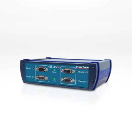
Type of the Interface |
USB | CAN |
|
USB-C |
USB 2.0 Full Speed |
|
Environmental |
|
Operating Range |
°C |
0 to 60 |
|
°F |
32 to 140 |
|
Mechanical |
|
Housing |
Aluminum |
|
Connection |
Plug connector |
|
Connection Type |
Sub-D44HD |
|
IP Rating |
IP50 |
|
Dimensions - W x L x H |
mm |
104.0 x 84.3 x 36.0 |
|
in |
4.09 x 3.32 x 1.42 |
U.S. dimensions and capacities are provided for conversion only. Standard products have International System of Units (SI) capacities and dimensions.
Dimensions
Dimensions
|
See Drawing |
Metric |
U.S. |
|
mm |
in |
|
(1) |
97.0 |
3.82 |
|
(2) |
40.3 |
1.59 |
|
(3) |
4.50 |
0.18 |
|
(4) |
84.3 |
3.32 |
|
(5) |
36.0 |
1.42 |
|
(6) |
2.0 |
0.08 |
|
(7) |
84.0 |
3.31 |
|
(8) |
104.0 |
4.09 |
|
(9) |
70.3 |
2.78 |
|
(10) |
M12 Socket |
|
(11) |
USB-C |
|
(12) |
D-Sub HD44 Connector (Sensor Input) |
|
(13) |
M12 Connector for CANbus |
U.S. dimensions and capacities are provided for conversion only. Standard products have International System of Units (SI) capacities and dimensions.
Connector Pin Diagram
Terminal Assignment
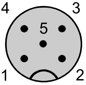
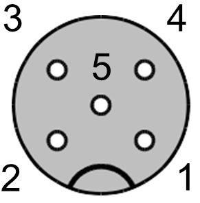 Pole pattern socket M12 for sensor connection
M12 Connectors with A-Coding
|
Pin No |
Terminal assignment |
ME
(Type 1) |
ME
(Type 2) |
Phoenix SAC-5P |
|
1 |
+US positive bridge power supply |
brown |
red |
brown |
|
2 |
-US negative bridge power |
white |
black |
white |
|
3 |
+UD positive bridge output / differential input |
green |
green |
blue |
|
4 |
-UD negative bridge output / differential input |
yellow |
white |
black |
|
5 |
TEDS connector |
grey |
|
grey |
A memory module (IEEE1451.4, template 33) written with TEDS data can be connected to pin 5 at channel 1 (CH1), the ground is connected to pin 2 (-Us).
Minimum necessary wiring: Pins 1 – 4 for bridge sensors.
 (Female)
(Male)
CANbus M12 5-Pin Female/Male A-Coded
|
Pin |
Name |
Meaning |
|
1 |
Shield |
Shielding |
|
2 |
V+ |
Power (UB+) |
|
3 |
V- |
GND (0V) |
|
4 |
CAN_H |
Dominant High |
|
5 |
CAN_L |
Dominant Low |
|
|
Case |
Shield |
For more information visit Electrical Wiring Diagrams

 In Motion Rail Weigh
  Friction Testing
  Printer Cartridge Seal
  Prosthetic Foot Performance


