Solution


In-Motion Rail Weigh

A rail station owner wanted to collect data on the load profiles for rail cars as they were entering into the station in-motion.


Summary

  • Customer Need / Challenge

    A rail station owner wanted to collect data on the load profiles for rail cars as they were entering into the station in-motion. The customer wanted to build their own low cost set-up using components from Interface and their existing PC setup for the purpose of logging weight load characteristics in order to diagnose possible side to side loading issues, overload issues, wheel flats or wheel impact issues, at any rail car speed.
  • Interface Solution

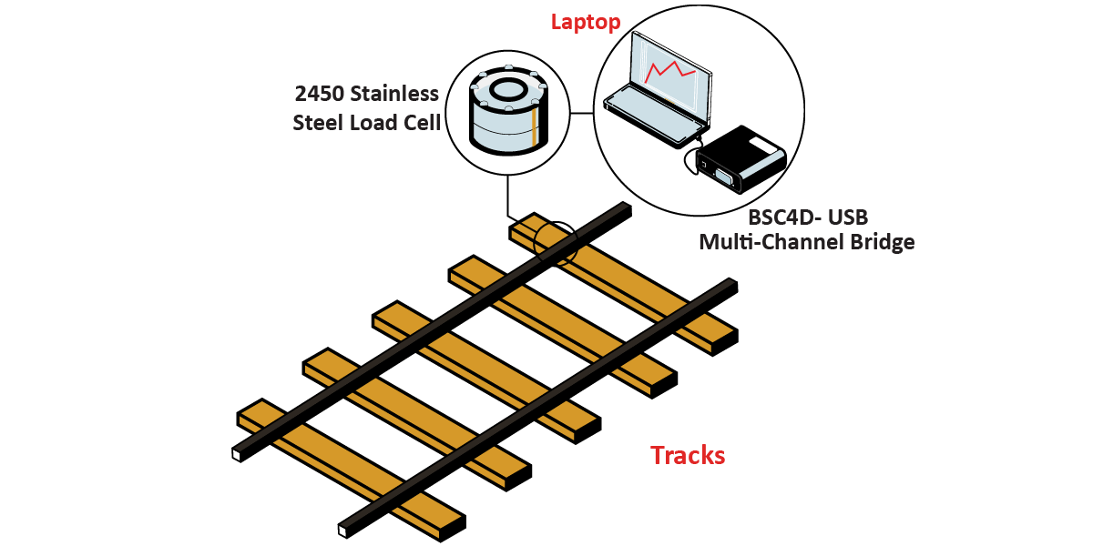
    (12) 2450 50K capacity standard stainless steel load cells were mounted in to metal fabricated box-like structures and bolted into six consecutive cement rail ties, one on each side of each tie under the rail with a direct line of force with the rail. The cells were split into three groups of four: front, middle, and back. Each group of cells was connected to a dedicated BSC4D that accepted four load cell inputs. The BSC4D were connected to a PC through a USB hub.

  • Results

    After all the connections were made the operator had a valuable tool for monitoring load characteristics which were used to detect a number of diagnostic conditions. The manager saved cost by creating his own set-up in-house for in-motion rail car load measuring as compared to alternative solutions from other competitors.

Materials


  • (12) 2450 50K capacity Standard Stainless Steel Load Cells

  • Three BSC4D-USB Multi-Channel Bridges

  • Amplifier & PC Interface Module

How it Works


  1. The customer made a special fixture that allowed for the mounting of the 2450 50K Capacity Standard Stainless Steel Load Cell. On the top there was a plate with a threaded rod which threaded into the load cell and on the bottom was an encasement that ensured proper clearance, stability, and proper enclosure from the elements.
  2. The cement rail ties were modified on both sides underneath the rail area to provide a recessed clearance for the cell fixtures. The fixtures were then fastened into the tie. Each tie has 2 fixtures. There were 6 ties altogether. There were two ties (four cells) per group: front, middle, and back.
  3. The load cells within the installed fixtures were connected via cables to the appropriate BSC4D -USB Multi-Channel Bridge Amplifier & PC Interface Module, using proper protective accessories and maintaining clearance from any potential snag or crush points.
  4. The interface modules were each connected to a PC through a USB hub.
  5. The PC had the BlueDAQ software installed that came with the interface modules.
  6. After the set-up was complete the operator had full access to logged load data from all 12 load cells which was used to diagnose rail-car issues.

Download PDF