Features and Benefits
- USB outputs
- 4 independent channels
- For use with model 3AXX series 3-axis load cells
- Can be used with up to any 4 standard load cells (with mV/V output)

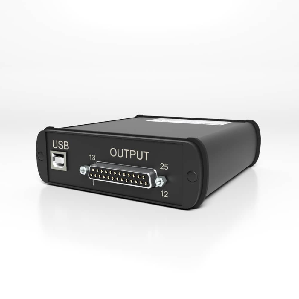
BSC4D Multi-Channel Digital PC Interface and Data Acquisition Instrument
The pricing listed on our website is only for U.S. buyers and all pricing is subject to change without notice. Any inquiries for products from buyers outside of the U.S. will receive a quote and availability from the licensed distributor nearest your region. These prices will be based on product availability, currency conversions, markets, taxes, shipping costs, as well as local support.
Model BSC4D Multi-Channel Digital PC Interface and Data Acquisition Instrument comes with a USB Interface. This product can be used with any mV/V input sensors including our Model 3AXX series 3-Axis Load Cells. Interface’s BlueDAQ logging, graphing and display software is included with the BSC4D.
Model BSC4D Multi-Channel Digital PC Interface and Data Acquisition Instrument comes with a USB Interface. This product can be used with any mV/V input sensors including our Model 3AXX series 3-Axis Load Cells. Interface’s BlueDAQ logging, graphing and display software is included with the BSC4D.
U.S. dimensions and capacities are provided for conversion only. Standard products have International System of Units (SI) capacities and dimensions.
U.S. dimensions and capacities are provided for conversion only. Standard products have International System of Units (SI) capacities and dimensions.
| Weight | 0.00 lbs |
|---|---|
| Dimensions | 6.65 × 4.17 × 1.25 in |
| Configurations |
U.S. dimensions and capacities are provided for conversion only. Standard products have International System of Units (SI) capacities and dimensions.
U.S. dimensions and capacities are provided for conversion only. Standard products have International System of Units (SI) capacities and dimensions.
| Weight | 0.00 lbs |
|---|---|
| Dimensions | 6.65 × 4.17 × 1.25 in |
| Configurations |
| Short Description | Sku | Price |
|---|---|---|
| Model BSC4-USB Multi-Channel PC Interface Module, USB Output, 37-pin D-Sub | BSC4D-D | $ 1,945.00 |
| Model BSC4-USB Multi-Channel PC Interface Module, USB Output, M-12 Circular x 4 | BSC4D-C | $ 2,065.00 |

 Mating Connectors

 In Motion Rail Weigh
  MARITIME Hydrofoil Testing in Wave Tank
  Friction Testing
  Printer Cartridge Seal
  OEM: Prosthetic Foot Performance