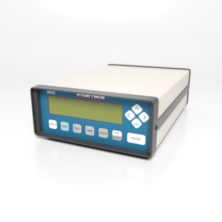
Features and Benefits
- Easy to navigate menus
- USB connection to PC with Windows DLL
- 3 relay setpoints or 1 alarm
- Digital input for print, reset, or tare
- Excitation sense
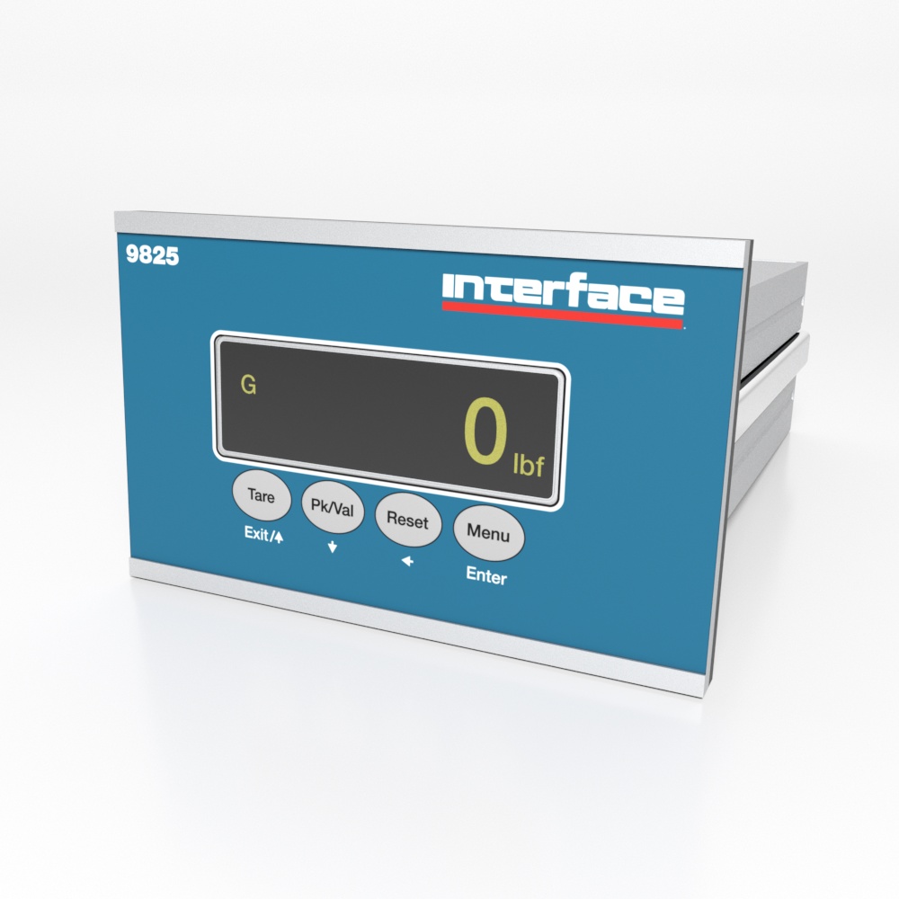
- Bipolar ±999,999 count display
- Nonlinearity < ±0.01%
- Analog output – 0-5V, 0-10V, 4-20mA, 0-24mA
- Calibration by live load or mV/V entry
- Peak and valley monitoring
- Front panel tare
- 30 readings per second (up to 1200 in FAST MODE)
- Digital filters