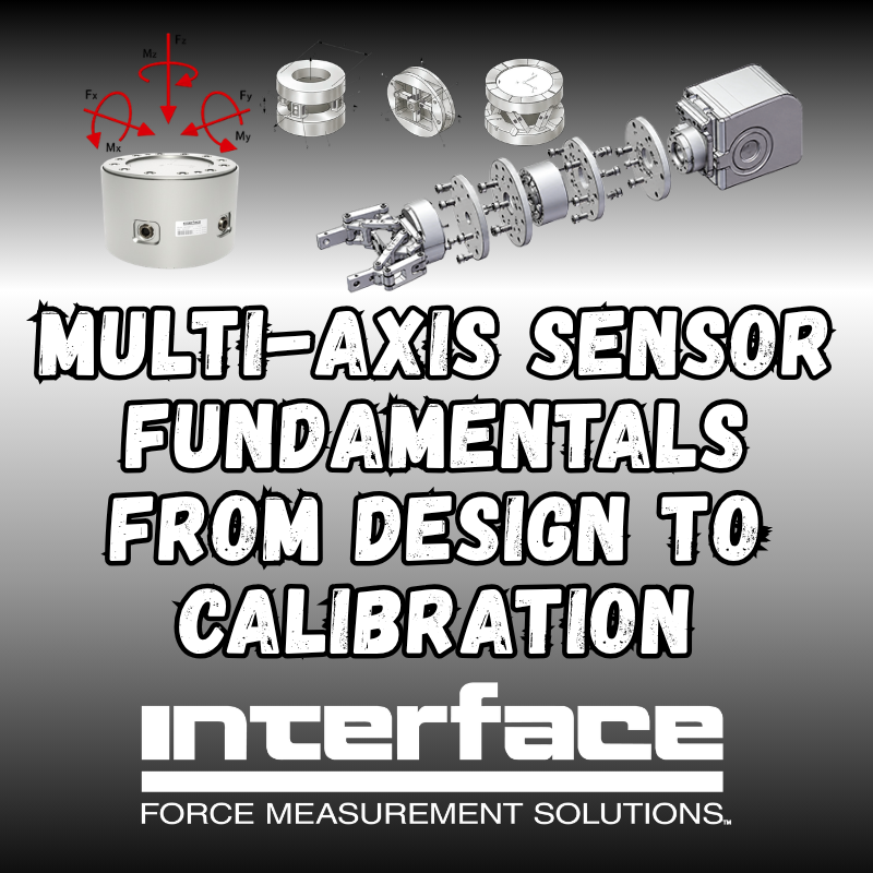
Multi-Axis Sensor Fundamentals from Design to Calibration
 Measuring forces in multiple directions is becoming increasingly common in test and measurement applications. While single-axis load cells are designed to measure force along a single axis, there is growing demand to measure forces, torques, and moments acting in multiple directions simultaneously. Multi-axis sensors are designed to solve this problem by capturing all forces and rotational motion simultaneously.
Interface has introduced a new online resource, Fundamentals of Multi-Axis Sensors, which provides technical articles to help readers understand these complex, multi-component devices. The online guide is structured into eight key areas:
- Intro to Multi-Axis Force/Torque Sensors
- 6-Axis Fundamentals
- 6-Axis Selection
- 6-Axis Assembly
- 6-Axis Calibration
- 6-Axis Accuracy
- 6-Axis Resolution
- 6-Axis Design

Understanding Multi-Axis Sensors
A multi-axis sensor is a device designed to measure forces and rotational forces (torques) in three directions simultaneously.
Traditional measurement devices typically measure force or torque in a single direction. In contrast, a multi-axis sensor captures the complete load on an object in real time in two-, three-, five-, or six-axis configurations. To do this, the sensor relies on internal electrical elements that measure physical stretching and bending. The raw signals from these elements are processed with a calibration matrix, a mathematical grid that maps the electrical signals to distinct force and torque values.
Interface 6-Axis load cell (6A and 6ADF) measures forces and moments in the three directions of the coordinate system. They consist of six strain gage full bridges. The six measurement signals are provided via a 24-pin connector for further processing with a measuring amplifier. To calculate the forces and moments, all six channels must be evaluated. The raw signal vector from the six strain gages is multiplied by a 6×6 matrix to output the isolated force (Fx, Fy, Fz) and moments (Mx, My, Mz). By comparison, Interface 3-Axis load cells integrate three single-axis force sensors into a single device, measuring Fx, Fy, Fz, and stiffness in a straightforward, compact design.
Multi-Axis Sensor Selection of Measuring Range
Choosing the right sensor is initially based on the required measuring range for forces and moments along the three coordinate axes. Other boundary conditions include geometry, installation constraints, accuracy, weight, and stiffness.
 In the Fundamentals of Multi-Axis Sensors section dedicated to selection, you can find a detailed 6-Axis Comparison Table that covers the Sensor Type, Dimensions, Mechanical Data, Electrical Data, and Characteristics of each Interface 6-Axis model.
Another resource is Interface’s Multi-Axis Sensor Selection Guide, which walks you through the selection process and helps you quickly evaluate sensor types based on the required axes and features such as tension and compression, axial torsion, side force, and flange mounting. It also details customization options, including connector protection, standardized output, TEDS, CANbus, internal shunt calibration, custom calibration, and multiple bridges.
Load Limits and Capacity Ratios
Multi-axis sensors have fixed capacity ratios because of their physical structure. For example, the vertical weight capacity is typically two to three times higher than the side-to-side capacity. This is because the internal structure distributes vertical loads across all of its support elements, while side-to-side loads are supported by only a few.
This ratio is important when an application requires measuring a very small force on one axis while a massive force is applied to another. For example, if you need to measure a friction force of ten Newtons under a vertical load of one thousand Newtons, you must use specialized calibration at that specific operating point to achieve accurate results.
Managing Crosstalk
When you apply force to one axis of a sensor, a small reading can appear on the other axes. This physical effect is called crosstalk.
In standard multi-axis sensors, this unwanted reading is typically about one percent of the load applied to the other axes. Crosstalk increases when forces are applied further from the sensor surface, leading to greater physical bending. Through specialized calibration at specific operating points, engineers can reduce this error to between 0.2% and 0.5%.
6-Axis Sensor Designs and Form Factors

Multi-axis sensor design begins with strain gage technology to convert mechanical deformation into an electrical quantity. The physical shape of the internal metal structure determines the force and torque measuring ranges. These structures generally fall into two categories:
Parallel Designs: These connect all internal support parts together to share the load. This configuration yields high stiffness, faster response to rapid changes in force, and a more compact physical size. Common parallel structures include:
- Solid or Hollow Cylinders: Sensing elements are arranged around a metal tube to calculate forces.
- Tripod (Vertical): Three vertical columns isolate torsion and radial forces from vertical loads.
- 4-Column (Vertical or Planar): Four pillars support high capacities, with planar versions used for silicon-etched microscale sensors that measure tiny forces.
- Hexapod (Stewart Platform): A six-legged structural frame designed to maximize overall strength and rigidity.
Series Designs: These stack the sensing elements one after another, such as a Measuring Cube. While this makes it easier to design and optimize each axis separately, the physical movement of each section adds up. This makes the overall sensor less stiff and more prone to crosstalk at the base.
Visit Interface’s Structure and Function of Force/Torque Sensors to explore the factors and the various ways strain-gage technology is used across different designs.
6-Axis Accuracy and Temperature Effects
A measuring device is accurate if it has high precision (repeatability) and high accuracy (closeness to the true value). The Interface Fundamentals of Multi-Axis section dedicated to accuracy provides a reference for the definitions of the accuracy class and measurement uncertainty.
Evaluating sensor performance requires understanding three basic accuracy concepts:
- Consistency and Linearity: This is how reliably the sensor repeats the same measurement, and how closely its output follows a straight line. High-quality sensors keep these deviations very low.
- Hysteresis: The difference between the sensor reading when a force is increasing and when it is decreasing. Minimizing this relies on flat mounting surfaces and secure bolting.
- Temperature Drift: Temperature changes cause the sensor materials to expand or contract, which can shift the zero point. High-quality sensors use materials that naturally compensate for temperature changes, keeping the drift below zero point five percent for every ten degrees of temperature change
Resolution
 Resolution is not the same as accuracy. Resolution is the smallest change in force the system can detect. Because resolution is largely determined by the measuring amplifier used, it is referenced to the amplifier’s standard measuring range (such as 2.0 mV/V).
Interface’s BlueDAQ software allows resolution to be displayed using various definitions, such as the difference between the maximum and minimum values over the last 10 seconds or the last 100 measured values. The resolution reference in the guide details the factors that influence resolution, including bandwidth, shielding, grounding, environment, and bridge supply voltage.
Calibration of 6-Axis Sensors
Calibrating a 6-axis sensor under partial load demonstrates the sensor’s accuracy within its actual operating range. Calibration with a maximum force of only 10% of the rated force is both feasible and advisable. Likewise, it may be advisable to perform calibration with a maximum of only 10% of the rated torque.
When calibrating at 1% of the rated load, the sensor’s deviation is not necessarily 100 times greater than when calibrating at the rated load. The result of calibration under partial load can even be better than calibration under nominal load. The calibration section of the new guide provides further details on reporting, amplification, and evaluation of results.
Assembly and Mounting

For a multi-axis sensor to function correctly, the end faces and flange plates must not deform. Even minor surface irregularities or uneven tightening can warp the mounting surfaces. This local deformation introduces mechanical pre-loads and parasitic stresses, directly degrading measurement accuracy.
When applying forces and moments, the load should be applied centrally and symmetrically. In the new guide’s Assembly section, learn about centering, flange types, flange plates, materials, and installation tips. Additionally, an inclusive table provides guidelines on flange plate material thickness and sensor mounting torques.
Engineering Tip: The Limitations of Combining Single-Axis Sensors
It is often tempting to combine several single-axis sensors to measure multi-directional forces. However, this approach introduces several mechanical issues in test and measurement applications.
#1: Reduced Stiffness – Stacking multiple individual sensors in a line reduces the system’s overall stiffness.
#2: Off-Axis Errors – Single-axis sensors are sensitive to forces applied at an angle, leading to measurement errors that are difficult to quantify.
#3: Friction Interference – Using mechanical guides to separate the forces introduces significant errors, often ten percent or more, due to static friction.
#4: Compact Integration – An integrated multi-axis sensor provides a simpler, stiffer, and more compact design with much higher accuracy.
To prepare for your next testing project, review the full Fundamentals of Multi-Axis Sensors guide for tips, resources, instructions, and references.
ADDITIONAL RESOURCES

A Promising Future in Measurement and Analysis Using Multi-Axis Sensors
Get Acquainted with Interface’s Expanding Line of Multi-Axis Sensors
The Power Combo of Multi-Axis Sensors Plus Instrumentation
X-Y-Z Robots and Multi-Axis Sensors are Advancing Automation
Examining Round and Square Multi-Axis Sensors
Controlling Crosstalk in Multi-Axis Force Measurement Systems
Dimensions of Multi-Axis Sensors Virtual Event Recap


