Load Cell Electrical Components, Connectors, and Wiring Standards
 In precision force measurement, the electrical pathway between the transducer and the instrumentation is as critical to data integrity as the sensor itself. If cables, connectors, or terminal connections introduce electrical noise or resistance, the accuracy of the entire measurement chain is compromised during use.
Understanding the electrical components, connector specifications, and wiring standards of load cells, torque transducers, and multi-axis sensors is essential for maintaining system accuracy and preventing equipment damage. To support load cell system integration, detailed documentation, including the Load Cell Cable Wiring Diagram, Load Cell Connector Wiring Diagram, and sensor wiring schematics, is available on individual product pages and compiled in the Interface Electrical Wiring and Diagrams support resource.
Transducer Electrical Components and Signal Behavior
Interface load cells use a Wheatstone bridge circuit composed of resistance strain gages bonded to a mechanical element. When a force is applied, the strain gages experience a change in electrical resistance. This change provides the data captured during measurements of force, torque, or weight.
Because strain gage bridges are passive networks, they require an external input voltage, typically ranging from 5V to 10V. The output from the bridge is a differential analog voltage measured in millivolts per volt (mV/V). At full capacity, a sensor with a 2 mV/V sensitivity operating on a 10V excitation voltage yields a maximum output of only 20 millivolts. Because this signal voltage is extremely low, it is highly susceptible to electromagnetic interference and attenuation. Using sensors that are designed to manage this type of noise is extremely important in your selection process.
Cable Configurations and Connector Definitions
The transition from the internal bridge circuit to the external data acquisition system requires specific cable designs and connection hardware.
Cable Types
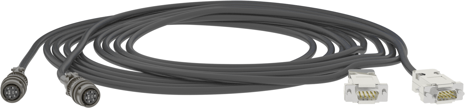
- 4-Wire Cables: This configuration includes positive and negative excitation lines and positive and negative signal lines.
- 6-Wire Cables: In addition to the excitation and signal lines, 6-wire cables include two sense lines. These lines monitor the exact voltage at the strain gage bridge, allowing the instrumentation to automatically compensate for voltage drops across long cable runs.
- Integral and Extension Cables: Integral cables are permanently bonded to the sensor housing during manufacturing, minimizing contact resistance. Extension cables connect to the sensor via a mating interface, extending the distance to the instrumentation.
Connectors and Mating Interfaces
- Connector Receptacle: The physical plug or receptacle mounted directly to the sensor housing. Standard designs often use multi-pin, bayonet connections to ensure physical security.
- Mating Connector: The corresponding plug is attached to the cable assembly that locks into the sensor receptacle. These assemblies often feature environmental seals to isolate the electrical pins from moisture and contaminants.
RESOURCES: Find our complete Sensor Interconnect Cable Assemblies Guide to help you define the right connection. Be sure to download our Cables and Connectors Brochure to keep on hand for future reference.
Cable Length and Wiring Modes
Cables have inherent electrical resistance that affects signal transmission with distance and configuration.
Resistance and Distance
In a 4-wire configuration, long cable lengths introduce an uncalibrated voltage drop across the excitation lines, reducing the voltage reaching the bridge and lowering the sensor output. For standard 28-gauge copper wire, this results in a sensitivity loss of approximately 0.37% per 10 feet. Because copper resistance varies with temperature, long 4-wire runs can exhibit thermal span drift as environmental temperature changes. Implementing a 6-wire configuration or calibrating the system with the exact cable length resolves this error.
Wiring Standards and Modes
Sensors are manufactured and wired for specific modes of operation, such as tension or compression. These standards define how the bridge outputs data relative to the direction of the applied load. Adhering to the correct upscale-mode wiring standard ensures that the instrumentation registers a positive value when the primary design force is applied, preventing mathematical errors in multi-cell configurations such as weighing platforms or structural test rigs.
TIP: Read Interface Cable Assemblies 101 for more information and Understanding Cable Length and Temperature Effects.
Wiring Color Matrices and System Protection
Adhering to a standardized wire color matrix is critical when terminating sensor connections at the instrumentation or junction box.
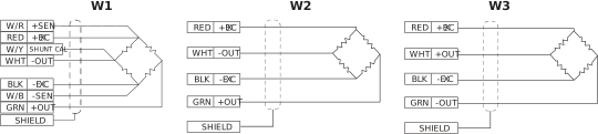
A common industry wiring standard uses the following layout:
- Red: Positive Excitation. This is the positive power input to the bridge.
- Black: Negative Excitation. This is the negative power input or ground.
- Green: Positive Signal. This is the positive millivolt output.
- White: Negative Signal. This is the negative millivolt output.
- Bare or Yellow: Shield. This is the ground line for electromagnetic shielding.
Due to the wide range of sensors and instrumentation, Interface provides cable and connector wiring/pin colors in many additional colors (up to 24 or more). You can find all the color guides for Interface wiring in online Electrical Wiring Diagrams Color-Coding references for Load Cells, Torque Transducers, 3-Axis Sensors, and 6-Axis Sensors.
Electrical Pitfalls of Incorrect Wiring
Errors during termination lead to predictable system failures. Here are three common errors.
#1 – Signal Inversion
Transposing the positive signal and negative signal wires does not damage the hardware, but it inverts the data output. Compression forces register as tension, which corrupts automated control loops.
#2 – Component Damage
An accidental cross-connection between an excitation line and a signal line can route power directly into the low-voltage measurement channels of the data acquisition system or across the delicate strain gages, often causing permanent electrical failure. If you have damaged your device, contact us immediately to aid in a repair.
#3 – Multi-Axis Complexity
Multi-axis sensors incorporate up to 24 separate pins and color codes across multiple channels. Verification of the exact connector pin diagram is mandatory before applying power to prevent cross-channel crosstalk or component burnout. Detailed schematics, including the 3-Axis Wire Color Coding, 3-Axis Round Wire Color Coding, and 6-Axis Wire Color Coding, are useful resources for verifying these complex multi-channel configurations.
Electrical Wiring and Cable Technical Resources
Achieving high-accuracy measurement data depends completely on the integrity of the electrical connections between the sensor and the instrumentation. Simple wiring errors or incorrect pin mapping can result in inverted data, thermal drift, or irreversible damage to components in the data acquisition system.
Technical specifications, pinouts, and wiring documentation are included on individual product pages across the website. For comprehensive reference materials, users can access Interface Support to find our dedicated Interface Electrical Wiring and Diagrams resource. This centralized library provides immediate access to specific reference matrices and schematics, including:
- Load Cell Cable Wiring Diagram
- Load Cell Connector Wiring Diagram
- Load Cell Wire Color Code
- Torque Transducer Wire Color Coding
- 3-Axis Wire Color Coding
- 3-Axis Round Wire Color Coding
- 6-Axis Wire Color Coding
For laboratory use, field reference, or system design integration, you can download the complete Interface Electrical Wiring Diagram Document to ensure exact compliance with factory wiring standards.
If you are unable to find the information you need to make the right connections between your sensor, cable, and instrumentation, contact Interface product experts for technical assistance.