
Moment 101
 A moment is the measure of a force’s tendency to cause rotational movement, bending, or tilting when applied at a distance from a fixed point or axis. In force measurement, motion is the physical displacement or rotation that occurs when an unbalanced force acts on an object.
Every applied load either creates straight-line motion, creates rotational motion, or generates internal stress when that movement is physically resisted. When a force acts directly through an object’s center, it creates pure linear movement. However, when that force is applied at a distance from a fixed point or central axis, it generates leverage, creating the physical tendency to bend, tilt, or tip a structure. Measuring force accurately across three-dimensional space requires evaluating both straight linear pushes and the moments created by off-axis loads.
Measuring Moment vs. Torque in Multi-Axis Sensors
A moment is the rotational effect produced when a force acts at a distance from a fixed point or central axis, attempting to bend, tilt, or tip a structure. Torque is a specialized subset of a moment in which the rotational force acts directly along the length of a central axis, causing a component to twist about its centerline.
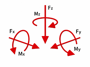
In a multi-axis sensor, complex loads are broken down across three perpendicular directions. Side-to-side and vertical linear forces are straight push or pull actions across the sensor’s surface and central height axis.
Bending moments measure the tipping or tilting forces that try to overturn the sensor around its horizontal axes. At the same time, torque isolates the pure twisting force applied around the central vertical axis. Understanding these combined loading directions allows engineers to evaluate the full rotational and linear stress profiles simultaneously.
How Moment Measurements Are Used in Testing
Sensors measure moments by detecting tiny amounts of stretch or compression within specialized internal metal structures. Rather than evaluating a single direction of force, moment measurements provide test engineers with a complete picture of complex mechanical behavior.
 By comparing the rotational bending force against the linear force, engineers can calculate the exact physical spot where an off-center force strikes a structure. This capability is essential for finding damaging bending stresses that cause mechanical components to break or fatigue over time, even when straight push-and-pull forces stay well within safe operating limits.
Furthermore, moment measurements supply real-time rotational feedback to automated control systems, allowing robotic end-effectors to continuously adjust their angle, position, or grip force when encountering unexpected off-axis resistance.
TIP: Learn more in Multi-Axis Fundamentals about force and moment measurements.
Five Technical Specifications for Sensors that Measure Moment
- Channel capacity: The maximum linear force or rotational bending force that a single measurement direction can safely handle.
- Signal output sensitivity: The electrical signal strength produced by the sensor at its maximum rated capacity, measured in millivolts of signal per volt of power supplied.
- Measurement deviation: The small degree of error between the actual applied load and the reading shown by the sensor, typically kept within a fraction of one percent.
- Channel interference: The small, unwanted signal generated on an unloaded measurement channel when a heavy force is applied to a different channel.
- Overload limit: The maximum amount of force or moment a sensor can absorb past its normal rating before internal parts permanently bend or break.
Engineering Considerations for Moment Measuring Multi-Axis Sensors
A moment is the general physical measurement of any rotational force produced when an applied load acts at a distance from a reference point or central origin. Depending on how that force vector aligns with an object’s geometry, a moment can cause a structure to tip, twist along its centerline, or flex across its cross-section. In multi-axis sensors, moments represent all rotational tendencies around three-dimensional space, providing a complete picture of how off-center or multi-directional forces interact with a physical system.
Designing and selecting multi-axis sensors that measure moments requires managing physical interactions between different force directions:
Internal Structure Design
Multi-axis sensors rely on specialized internal metal structures designed to isolate different types of movement. Some designs use a single solid piece of metal shaped to handle linear forces and rotational moments together, while others stack simpler single-direction sensors within a combined frame.
Signal Correction Calculations
Because a single physical structure bends slightly under any load, an applied force in one direction can cause tiny physical shifts in another direction. To correct for this channel interference, multi-axis sensors use processing algorithms that combine all bridge outputs to extract the true force and moment values.
Handling Combined Off-Center Loads
In real-world operations, forces rarely act in isolation. An off-center push creates both a linear force and a bending moment. Engineers must calculate the combined stress from all active forces to ensure the total load does not exceed the sensor’s structural limits.
REMINDER: A bending moment is a specific type of moment that acts perpendicular to the primary axis of a structural component or sensor. Instead of twisting an object around its length, a bending moment attempts to curve, bow, or overturn the structure. This action creates simultaneous tension on one side of the internal flexure and compression on the opposite side, which specialized strain gage bridges detect to isolate and measure off-axis bending loads.

Interface Force and Moment Sensor Models
Interface offers several multi-axis sensor lines designed to measure simultaneous forces and moments.
2-Axis Sensors
- TXY Load Cells measure forces simultaneously along two perpendicular axes (X and Y) to evaluate dual-direction bending or sliding loads.
3-Axis Sensors
- 3A Series (3A40, 3A120, 3A160, 3A300) are square 3-axis sensors that measure linear forces along X, Y, and Z axes simultaneously.
- 3AR Series are round 3-axis force sensors designed for compact spaces and low channel interference across all three axes.
- 3AFM Series are 3-axis force and torque load cells that measure combined linear forces and rotational forces in a single unit.
- 5200XYZ is a LowProfile 3-axis load cell designed to measure moment loads along with axial loads to determine center of gravity or misalignment.
6-Axis Sensors
- 6A models 6A27, 6A40, 6A68, 6A150, 6A225, and 6A300 are monolithic 6-axis load cells that measure all six components simultaneously: three linear forces (Fx, Fy, Fz) and three rotational moments/torques (Mx, My, Mz).
TECHNICAL NOTE: A calibration matrix is needed to calculate the forces and moments from the six measurement signals. The calibration matrix defines the relationship between the six measurement signals and the forces Fx, Fy, Fz, and the moments Mx, My, and Mz. Using special calibration matrices (Matrix Plus) can improve accuracy and minimize crosstalk for a specific load case.
Examples of Moment Applications
Industries from automotive to aerospace use moment measurements for a variety of testing applications. Here are a few examples.
#1 – Robotic arm joint moment measurements to better understand how the mechanical arm extends outward to pick up an object. The weight creates a strong bending moment at the wrist joint. Measuring this moment keeps the arm stable.
#2 – Aircraft wing testing requires measuring moments. Wind exerts upward lift along the wing’s surface, creating a bending moment at the wing’s attachment to the aircraft’s body. Measuring this bending moment confirms structural strength.
#3 – Vehicle wheel moment testing is valuable for automotive testing. When a vehicle turns a sharp corner, friction pushing sideways on the tire generates a bending moment on the wheel hub, in addition to the vehicle’s vertical weight.
#4 – Human movement studies are used in various medical and healthcare applications. Evaluating artificial knee or hip joints requires measuring both the vertical downward force of a footstep and the bending moments caused by twisting or changing direction.
Value of Measuring Moment
Moment measurements using multi-axis sensors eliminate guesswork by providing a complete, three-dimensional picture of physical forces. Instead of assuming forces act in a single straight line, these tools measure linear pushes, pulls, bending moments, and twisting torque simultaneously from a single location.
Measuring moments provides complete visibility, allowing engineers to catch unexpected structural stresses, build safer machines, optimize mechanical designs for weight and durability, and give automated systems the precise physical feedback required to navigate complex real-world environments.
ADDITIONAL REFERENCE