Specifications
Specifications
U.S. dimensions and capacities are provided for conversion only. Standard products have International System of Units (SI) capacities and dimensions.
Connector Pin Diagram
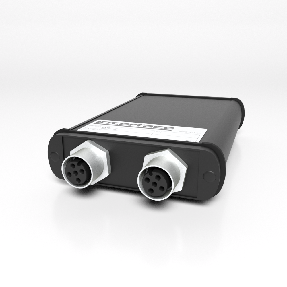
Connectors
Two Connectors M12 5-Pin, Female Available
| PIN ASSIGNEMENT (FULL-, HALF, QUARTER BRIDGES, DISTANCE SENSORS) |
| PIN | FUNCTION | COLOR |
| | GND (= -US) | SHIELING |
| 2 | -US Negative Bridge Power Supply | WHITE |
| 1 | +US Positive Bridge Power Supply | BROWN |
| 3 | +UD Positive Differential Input | GREEN |
| 4 | -UD Negative Differential Input | YELLOW |
| 5 | AUXin Customisable Input | GRAY |
| | TARE Control Input For Zero Setting Function | |
| | VCC_T Voltage 5.6V DC, 1mA | |
| | SW Threshold Switch | |
- In the 2-channel BSC2 with a round plug connector, the shield is placed on the plug housing.
- Alternatively, the shield is placed on PIN 2 of the round plug connector.
Connection diagram for quarter bridges and half bridges
Please note: When connecting quarter or half bridges, the measuring amplifier must be correctly configured. Closing two solder bridges connects together the three additional resistors.
Wire strain gauge-quarter bridges are connected using three-wire technology, which reduces the impact of the supply cable on the zero point, and halves zero point drift.
Connection diagram for potentiometric distance sensors
The BSC2 measuring amplifiers are avaialble in a design for connection to potentiometric distance sensors (linear potentiometer or tackle way receiver), which involves the slider of the distance sensor being conneted to the “Aux” input of the measuring amplifier.
The distance sensor is powered via the sensor power supply +Us and -Us.
Distance Sensor
The potentiometric distance sensor is connected between +Us, -Us and AUX.
The power supplied to the potentiometric distance sensor is at 4.2V.
The input scope includes the ability to handle voltages of 0 – 4.2V.
Terminal Assignment
| DESIGNATION | 5-POLE SOCKET BSC2 |
| +Supply +Us | 1 |
| -Supply +Us | 2 |
| Input "Aux" | 5 |
Connection of Sensors with ±10 Volt Output
| DESIGNATION | 5-POLE SOCKET BSC2 |
| ±10 Volt | 3 |
| Measuring Signal Mass | 4 |
| Shield | Housing |
Terminal Assignment for Current Input
| DESIGNATION | 5-POLE SOCKET BSC2 |
| ±20 mA | 3 |
| Measuring Signal Mass | 4 |
| Shield | Housing |
Speed Measurement
BSC2 measuring amplifiers are available in models capable of measuring speed. This involves the connection of a hall switch as a sensor, which is triggered by one, two, four or eight magnets per revolution. The threshold level at which the speed measurement pulse is detectable is a change in the magnetic flow density from 20mT to 4mT, whereby the magnetic south pole must be facing the sensitive surface of the hall switch.
The unit must be configured to rpm and the output reading of the measurement values is set to text format by default. The default scaling is set to 20000 and cannot be changed. The number of magnets generating pulses on the hall sensor .can be configured using gsvterm.exe. For this purpose, please use the menu option “Special settings“ within the program interface refer to the BSC2 Dual Channel PC Interface Module Manual, Page 2.
Connection of the HAL501 Hall Switch
| DESIGNATION | 5-POLE SOCKET BSC2 | HAL501, Customized |
| Mass (GND), Shield | 2 | Brown |
| Supply +5V | 1 | White |
| Hall Switch Signal | 3 | Green |
Instead of the HAL501 hall switch, other transmitters with a power consumption under 5V, 5mA and an output signal with TTL Pegel can be connected.
The use of a rod magnet NdFeB 20mmx10mmx4mm enables a working distance of up to 10mm between the hall switch and the magnet.
| NUMBER OF MAGNETS | SPEED RANGE IN RPM | RESPONSE TIME IN TERMS OF NUMBER OF ROTATIONS |
| | MINIMUM | MAXIMUM | MINIMUM | MAXIMUM |
| 1 | 18 | 36000 | Around 1 | Around 2 |
| 2 | 9 | 18000 | Around 1/2 | Around 1 |
| 4 | 4.5 | 9000 | Around 1/4 | Around 1/2 |
| 8 | 2.25 | 4500 | Around 1/8 | Around 1 |
Hall switch HAL501 within the TO92 housing, note the sensitive surface position (should be facing the magnetic south pole)
Connection of Dual Track Pulse Generators
BSC2 measuring amplifiers are available in models capable of measuring rotation angle/speed or travel distance. For this purpose, an incremental pulse generator is connected, which emits phase-shifted square signals in the event of a change in travel distance or rotation angle through 90° (connections A and B).
| FUNCTION | 5-POLE SOCKET BSC2 |
| Mass (GND), Shield | 2 |
| Supply +5V | 1 |
| Pulse Signal A | 3 |
| Pulse Signal B | 4 |
Connection of a Torque Sensor
A dual-channel measuring amplifier BSC2-5 10mV/V/RPM/Sub-D15 is recommended for operating the torque sensor.
Lines “A” to “M” of the torque sensor are connected to the SubD-15 socket of the measuring amplifier.
Configuration
| PORT "A" | PORT "B" |
| "Log Mode" Off | "Log Mode" On |
| Scaling factor 2 mV/V or a corresponding factor calculated for the sensor parameter. | Scaling factor 31207.6 for the display in angular degrees. The resolution is 0.5°. |
The data frequency is configured to port “A” . Port “B” transmits synchronously with the data frequency of port “A”.
Port “B” functions as an incremental counter and is not automatically reset to zero. After reaching the figure 65535°, it reverts to zero.
The command “SetZero” can be used to reset the counter to 0 at any time.
| TORQUE SIGNALS | TORQUE 12-POLE PLUG CONNECTOR | BSC2 5-POLE M12 SOCKET; PORT "A" | BSC2 5-POLE M12 SOCKET; PORT "A" |
| Strain Gage Us+ | B | 1 (Brown) | - |
| Strain Gage Us- | A | 2 (White) | - |
| Strain Gage Ud+ | C | 3 (Blue) | - |
| Strain Gage Ud- | D | 4 (Black) | - |
| Counter +5V (Vcc) | F | - | 1 (Brown) |
| Counter GND | E and J (Where applicable, connected) | - | 2 (White) |
| Counter A | G | - | 3 (Blue) |
| Counter B | H | - | 4 (Black) |
| Shields | M | Cable Shield | Cable Shields |
For more information visit Electrical Wiring Diagrams