Features and Benefits
- Provides limit switching
- Two relays mains rated
- Accepts up to 16 devices
- Provides a range of relay operation modes
- Loss of signal alarm relay
- Latch and inversion options for all relays
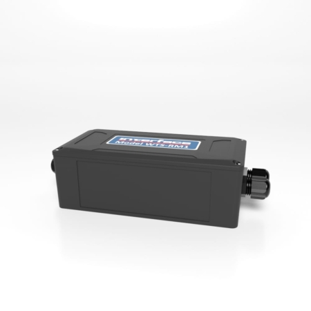
WTS-RM1 Wireless Relay Output Receiver Module

The pricing listed on our website is only for U.S. buyers and all pricing is subject to change without notice. Any inquiries for products from buyers outside of the U.S. will receive a quote and availability from the licensed distributor nearest your region. These prices will be based on product availability, currency conversions, markets, taxes, shipping costs, as well as local support.
Wireless Relay Output Receiver Module acts on data from any of the WTS wireless transmitter modules and can be used for alarm and control purposes forming part of the WTS modular telemetry system.
The data sent by transmitter modules can be utilized by multiple receivers such as displays, handheld readers, analog outputs, relay modules and computer interfaces. Receivers support common industrial power supplies and are available in robust IP rated enclosures with internal antennas optimized to give outstanding coverage.
The WTS-RM1 offers two single pole changeover relays with mains rated 5 amp contacts for power switching. Functionality includes set-points, inversion, latching and hysteresis. The WTS Toolkit offers a fast and simple way to configure the relays operation and set-point values, which are entered in the engineering units of the associated transmitter modules.
U.S. dimensions and capacities are provided for conversion only. Standard products have International System of Units (SI) capacities and dimensions.
U.S. dimensions and capacities are provided for conversion only. Standard products have International System of Units (SI) capacities and dimensions.
| Weight | 0.00 lbs |
|---|---|
| Dimensions | 6.50 × 3.30 × 2.20 in |
| Configurations |
U.S. dimensions and capacities are provided for conversion only. Standard products have International System of Units (SI) capacities and dimensions.
U.S. dimensions and capacities are provided for conversion only. Standard products have International System of Units (SI) capacities and dimensions.
| Weight | 0.00 lbs |
|---|---|
| Dimensions | 6.50 × 3.30 × 2.20 in |
| Configurations |

 WTSSHK-B-HL Wireless Bow Load Shackle
 We use cookies to enhance your browsing experience, serve personalized content, and analyze our traffic. By clicking "Accept All Cookies", you consent to our use of cookies.
Accept All CookiesReject AllCookie SettingsWe may request cookies to be set on your device. We use cookies to let us know when you visit our websites, how you interact with us, to enrich your user experience, and to customize your relationship with our website.
Click on the different category headings to find out more. You can also change some of your preferences. Note that blocking some types of cookies may impact your experience on our websites and the services we are able to offer.
These cookies are strictly necessary to provide you with services available through our website and to use some of its features.
Because these cookies are strictly necessary to deliver the website, you cannot refuse them without impacting how our site functions. You can block or delete them by changing your browser settings and force blocking all cookies on this website.
These cookies collect information that is used either in aggregate form to help us understand how our website is being used or how effective our marketing campaigns are, or to help us customize our website and application for you in order to enhance your experience.
If you do not want us to track your visit to our site, you can disable tracking in your browser here:
We also use different external services like Google Webfonts, Google Maps and external Video providers. Since these providers may collect personal data like your IP address we allow you to block them here. Please be aware that this might heavily reduce the functionality and appearance of our site. Changes will take effect once you reload the page.
Google Webfont Settings:
Google Map Settings:
I agree to the terms and conditions laid out in the Privacy Policy


Please share your location to continue.
Check our help guide for more info.
