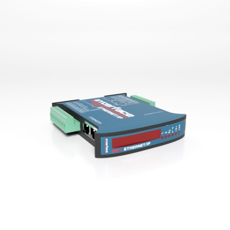
WTS-GW1 Wireless Gateway with Modbus and ASCII Serial Output
Wireless Gateway with Modbus and ASCII Serial Output
The WTS-GW1 is a gateway that provides a standard serial interface to gather data from up to 100 transmitter modules in a WTS telemetry system using either the Modbus RTU protocol or a simple ASCII protocol.
The data sent by transmitter modules can be utilized by multiple receivers such as displays, handheld readers, analog outputs, relay modules and computer interfaces. Receivers support common industrial power supplies and are available in robust IP rated enclosures with internal antennas optimized to give outstanding coverage.
The WTS-GW1 supports RS232 and RS485 connectivity. Some simple commands are available to wake, sleep, and keep awake WTS transmitter modules.
The WTS Toolkit software offers a fast and simple way to configure the gateway module.
Please Login to view pricing and product downloads
Need a quote or looking to purchase this item?
Login, scroll to see your model descriptions and SKU part number, then use the Request for Quote button to submit your request.
