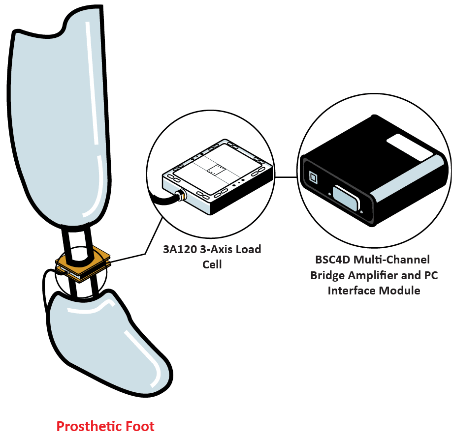
Customer would like to know how a prosthetic foot responds as it is loaded during different stances.
Interface Solution
Interface’s 3A120 3-Axis Load Cell was installed between the leg socket and the prosthetic foot. The 3A120 was then connected to the BX3-HD44-CAN 3-Channel CANbus AND USB Strain Gage Amplifier to determine and collect data points.
Results
Data was logged for X, Y, and Z axis. Customer was able to review the results and identify premature foot flat and dead spots during foot’s use. They can now make improvements to the design.
Materials
3A120 3-Axis Load Cell
BX3-HD44-CAN 3-Channel CANbus AND USB Strain Gage Amplifier
Prosthetic foot undergoing test
How it Works
Install the 3A120 into prosthetic foot load stream. The BX3-HD44-CAN 3-Channel CANbus AND USB Strain Gage Amplifier collects the force readings where it can be displayed and monitored when conneced to the customer’s computer with supplied BlueDAQ sofware.
Review X, Y and Z force measurements to determine foot flat and dead spots with customer instrumentation.
We use cookies to enhance your browsing experience, serve personalized content, and analyze our traffic. By clicking "Accept All Cookies", you consent to our use of cookies.
We may request cookies to be set on your device. We use cookies to let us know when you visit our websites, how you interact with us, to enrich your user experience, and to customize your relationship with our website.
Click on the different category headings to find out more. You can also change some of your preferences. Note that blocking some types of cookies may impact your experience on our websites and the services we are able to offer.
Essential Website Cookies
Essential Website Cookies
These cookies are strictly necessary to provide you with services available through our website and to use some of its features.
Because these cookies are strictly necessary to deliver the website, you cannot refuse them without impacting how our site functions. You can block or delete them by changing your browser settings and force blocking all cookies on this website.
Google Analytics Cookies
Google Analytics Cookies
These cookies collect information that is used either in aggregate form to help us understand how our website is being used or how effective our marketing campaigns are, or to help us customize our website and application for you in order to enhance your experience.
If you do not want us to track your visit to our site, you can disable tracking in your browser here:
Other external services
Other external services
We also use different external services like Google Webfonts, Google Maps and external Video providers. Since these providers may collect personal data like your IP address we allow you to block them here. Please be aware that this might heavily reduce the functionality and appearance of our site. Changes will take effect once you reload the page.
Google Webfont Settings:
Google Map Settings:
Privacy Policy
Privacy Policy
I agree to the terms and conditions laid out in the Privacy Policy