
Mounting Tips for Multi-Axis Sensors
Understanding best practices for mounting is critical to collecting accurate data, especially when it comes to multi-axis load cell solutions. As more testing engineers choose multi-axis sensors for the benefits of additional data, it is important to note that improper mounting can cause multiple axis to be unaligned and skew the data across the various axis you are measuring.
In follow-up to our webinar, Inventive Multi-Axis and Instrumentation Webinar, here are some valuable reminders on how to properly mount both 3-Axis and 6-Axis load cells to gather the most accurate and reliable data for any test and measurement application.
The first thing to understand is there are certain mounting considerations that are important across every type of multi-axis sensors. These considerations begin with understanding the relationship between the sensor and mounting hardware. The sensor is made up of the electronic internals of a load cell, while the mounting hardware is comprised of plating that needs to align with the test system.
The next thing to understand is that deflections in the system introduce errors and apparent crosstalk. To avoid deflections, plates and fixtures used in mounting must be stiff enough to avoid deflections. The best way to understand this is to try and emulate how stiff the plating was when the sensor was calibrated, this will help you understand how stiff you need the plate to be in the testing application.
Finally, every single multi-axis sensor model also comes with unique mounting instructions, so be sure to consult the written instructions if you have questions. When it comes to mounting instructions for our products, Interface publishes all mounting instructions online.
Mounting instructions provide information on the class of hardware for mounting, as well as important data such as the torque on the dowel pins, for cases that include dowel pins.
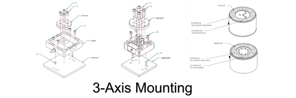 For 3-axis mounting, we provide assembly instructions for each type of load cell available. For example, the assembly instructions pictured on the far left shows a 3-Axis sensor with four threaded mounting holes on the top surface and two dowels that should be used to avoid the plate slipping. The dowel pins are crucial to aligning the axis. The instructions also show mating services which are identified with arrows or hash marks.
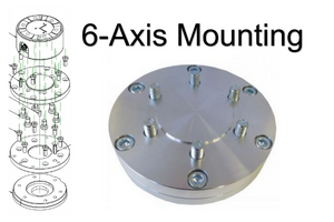 The 6-axis mounting hardware is a bit different in that there are more holes in the mounting plates and fixtures for dowel pins, which stop the mounting plate from deforming or bending because this can cause inaccuracies in data. Additional mounting locations are necessary to securing the plates and fixtures.
Considerations for 6-axis mounting include the potential need to use a double-plate mounting arrangement, the plates must be suitably thick, the plates must have the same material as sensor for thermal matching, and flat and smooth mounting plate surfaces are preferred. The example here shows some of the features mentioned above.
We hope this simple guide will provide you with the information you need to get the most out of your multi-axis sensors. If you are ever unsure about any details within the mounting process for multi-axis sensors, feel free to contact Interface for support or questions about any multi-axis products.
ADDITIONAL RESOURCES
Interface Multi-Axis Sensor Market Research
Dimensions of Multi-Axis Sensors; An Interface Hosted Forum


