
Strain Gage Interconnection to Bridge Configurations for Load Cells
 Strain gages are fundamental to load cell technology, converting mechanical force into measurable electrical signals. Interface defines the gage interconnection in our essential Load Cell Field Guide.
The interconnection of strain gages in a Wheatstone bridge—forming quarter, half, or full bridges—is a critical design choice that impacts performance, cost, and application suitability.
When thousands of gages are needed to implement an extensive test, the quarter bridge configuration is a cost control necessity. The only active bridge leg (a strain gage) and the other three inactive legs are fixed resistors, simulating a complete bridge. Other parameters being equal, a full bridge has twice the output of a half bridge and four times that of a quarter bridge.
This overview provides an engineer’s perspective on these configurations, drawing upon established principles in the field.
The Core Principle: Strain to Resistance
As Interface’s field guide emphasizes, the foundation of strain gage technology lies in the principle that a gage’s electrical resistance changes proportionally to the applied strain. This relationship is quantified by the gage factor (GF): RΔR=GF⋅ϵ
This change in resistance, though small, is precisely measured using a Wheatstone bridge circuit, the standard method for converting this electrical variation into a usable voltage output.

Balancing Bridge Configurations to Application Needs
Interface’s experience in building standard and custom load cells for nearly 58 years notes that selecting a bridge configuration is a strategic decision, balancing initial cost with desired sensitivity and the necessity of mitigating environmental factors and extraneous mechanical loads.
Quarter Bridge: Simplicity for Specific Cases
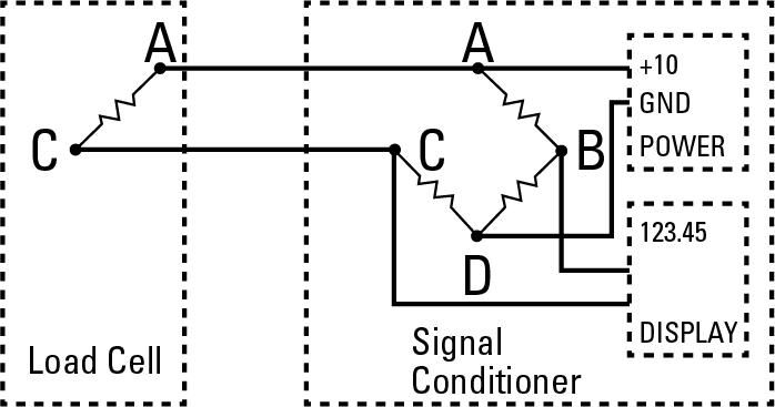 A single active strain gage is integrated with three fixed resistors to complete the Wheatstone bridge. The bridge’s output voltage directly reflects the resistance change of this one active gage. Established load cell design practices recommend that the quarter bridge offers the most economical initial setup due to the single active sensing element. Its simplicity can be advantageous in cost-sensitive applications where stringent accuracy and stability are not paramount.
While cost-effective, quarter bridges exhibit the lowest sensitivity, making the signal more noise resistant. They are also susceptible to temperature fluctuations, potentially causing zero-point drift. Compensation for bending or torsional loads is minimal.
TIP: Quarter bridges are typically utilized for simple weighing devices without high precision, fundamental stress analysis under controlled conditions, and educational tools illustrating strain measurement principles. Interface’s guidance suggests limiting this configuration to applications where environmental stability and load purity are less critical.
Half Bridge: Enhanced Performance through Gage Pairing
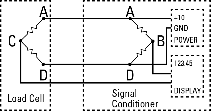 Two active strain gages, strategically mounted on the load-sensing element, are paired with two fixed resistors in the bridge circuit. The output voltage is proportional to the combined resistance changes of the two active gages. Often, these gages are oriented to experience opposing strains under load, effectively doubling the output compared to a quarter bridge.
Interface’s load cell engineers underscore that the half bridge offers a significant step up in performance. Employing two active gages provides higher sensitivity and the potential for inherent first-order temperature compensation, provided both gages experience similar temperature variations. Careful placement of the gages can reduce sensitivity to center off-axis loads, a key consideration in load cell design.
Installation is more complex than a quarter bridge. Adequate temperature compensation relies on matched gage characteristics and uniform temperature distribution. The ability to reject specific extraneous loads depends heavily on the precise location and orientation of the two active gages on the sensing element.
TIP: Integrated load cells where the system design can accommodate specific mounting and signal processing for enhanced stability, force measurement in predominantly uni-axial loading scenarios where some bending might be present, and custom sensor designs aiming for improved sensitivity over a quarter bridge.
Full Bridge: The Apex of Performance and Compensation
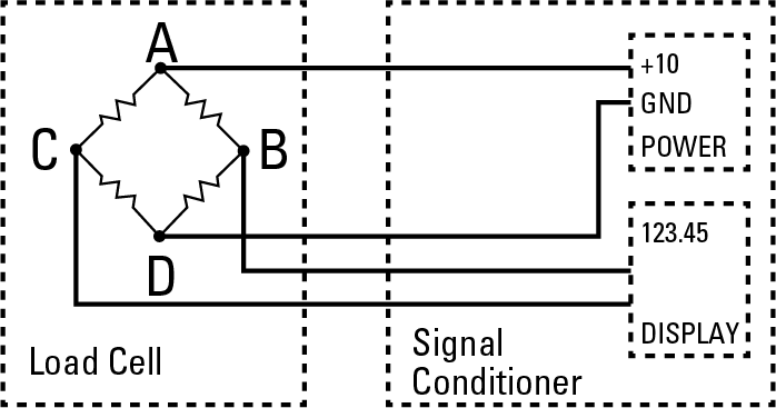
Four active strain gages form all four arms of the Wheatstone bridge circuit. The output voltage is proportional to the sum of the resistance changes of all four gages, maximizing sensitivity. Typically, two gages are placed to sense tensile strain, and two to sense compressive strain under the applied load.
Interface’s extensive experience positions the full bridge as the premier configuration for high-accuracy and high-stability load cells. Its inherent compensation for temperature effects on zero and span, and its ability to be designed for minimal sensitivity to off-axis loads and bending moments through strategic gage placement, make it the standard for demanding applications. This configuration yields the highest sensitivity and linearity.
These devices are considered premium and worthy of a long-term investment because they use four active gages and have a more intricate installation process. Superior performance often justifies this asset for applications that require reliable and precise measurements.
TIP: Industrial weighing systems, precision force measurement in material testing and calibration, aerospace and automotive testing where complex loading and temperature variations are standard, high-performance scales for legal-for-trade applications, and critical process control systems. Interface’s load cell offerings in these areas predominantly utilize full bridge configurations to ensure optimal performance.
Bridges and Gage Interconnection Key Engineering Takeaways
Interface’s long-standing experience in load cell design and manufacturing emphasizes that the choice of strain gage bridge configuration is a fundamental engineering decision driven by the specific application requirements.
Factors such as necessary accuracy, anticipated operating environment, potential extraneous loads, and budget constraints must be carefully weighed. While quarter bridges offer initial cost savings, the enhanced performance and inherent compensation capabilities of half- and particularly full-bridge configurations often provide the most reliable and accurate long-term solutions for demanding force and weight measurement applications.
Understanding these trade-offs, informed by the principles highlighted in resources like Interface’s Load Cell Field Guide, is essential for engineers across various disciplines.

Watch the Interface’s Load Cell Design Webinar for more technical insights into bridge and strain gage configurations.


