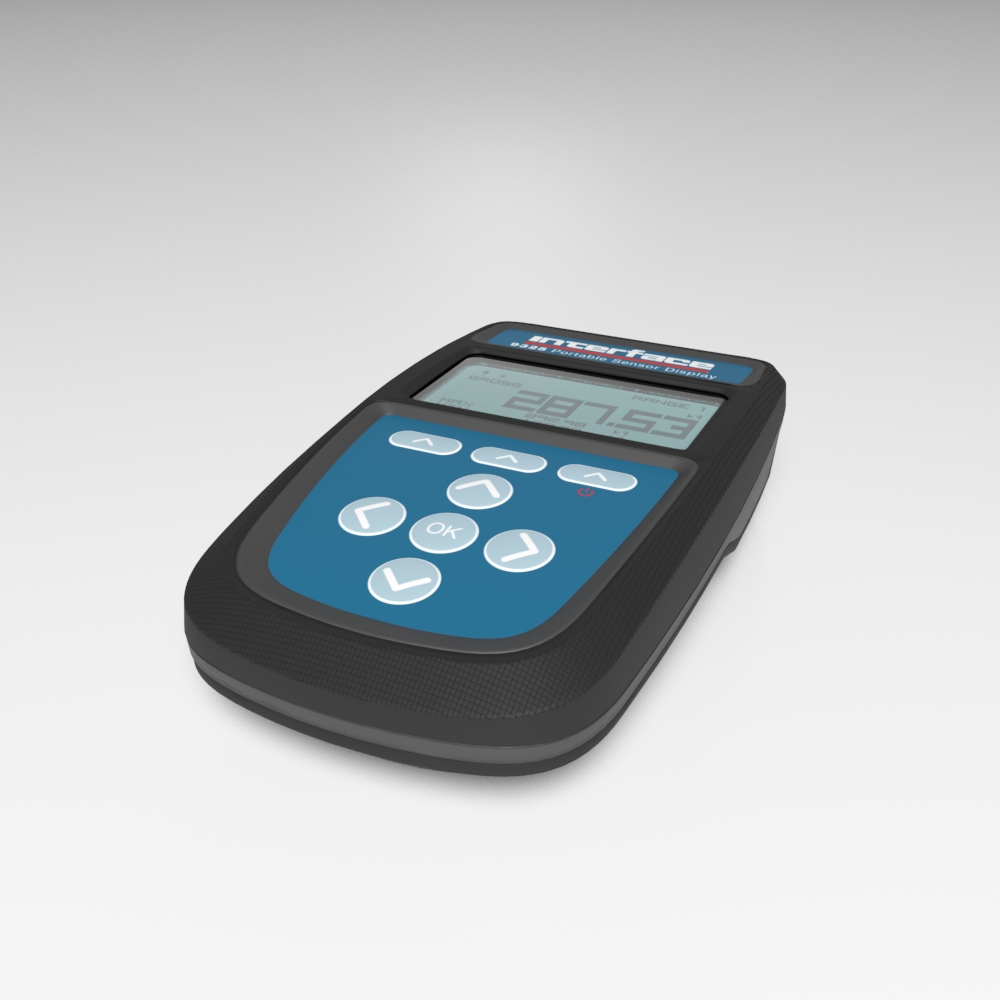
Features and Benefits
- USB port providing configuration, calibration, save & restore, live logging
- Superior Linearity Performance Specifications
- Measurement Rate up to 2400 Samples per Second
- High Internal Resolution (up to 500,000 counts)
- IP64 Environmentally Protected Enclosure
- Battery Powered (Long Battery Life)
- 128 x 64 Graphical Display with Backlight
- Multiple Display Modes (Peak/Valley, Delta, Live, Gross and Net)
- Logging and Graphing to PC (Software is Included)
- Supports TEDS Template 33, 40 and 41
- Live Calibration and Multi-point Calibration
- Standard Audio Alarm
- CE Environmental Approved
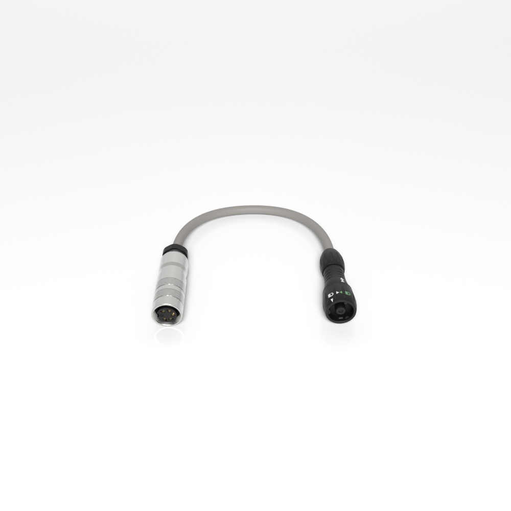
Connection Options
- Model 9325 to Bayonet-type Connection Cable
- Model 9325 to Screw-type Connection Cable
- Model 9325 to D Sub Connection Cable
- Add Mating Connector to Integral Transducer Cable
- Custom Cables
Accessories
- USB Right Angle Cable 1M
- Screw Mounting Kit with Articulating Arm
- Suction Mounting Kit with Articulating Arm


