Features and Benefits
- Controllable baud rates
- Configure & calibrate the WTS devices
- USB/RS232/RS485 interface
- Rugged enclosure
- Data collection for PC/PLC
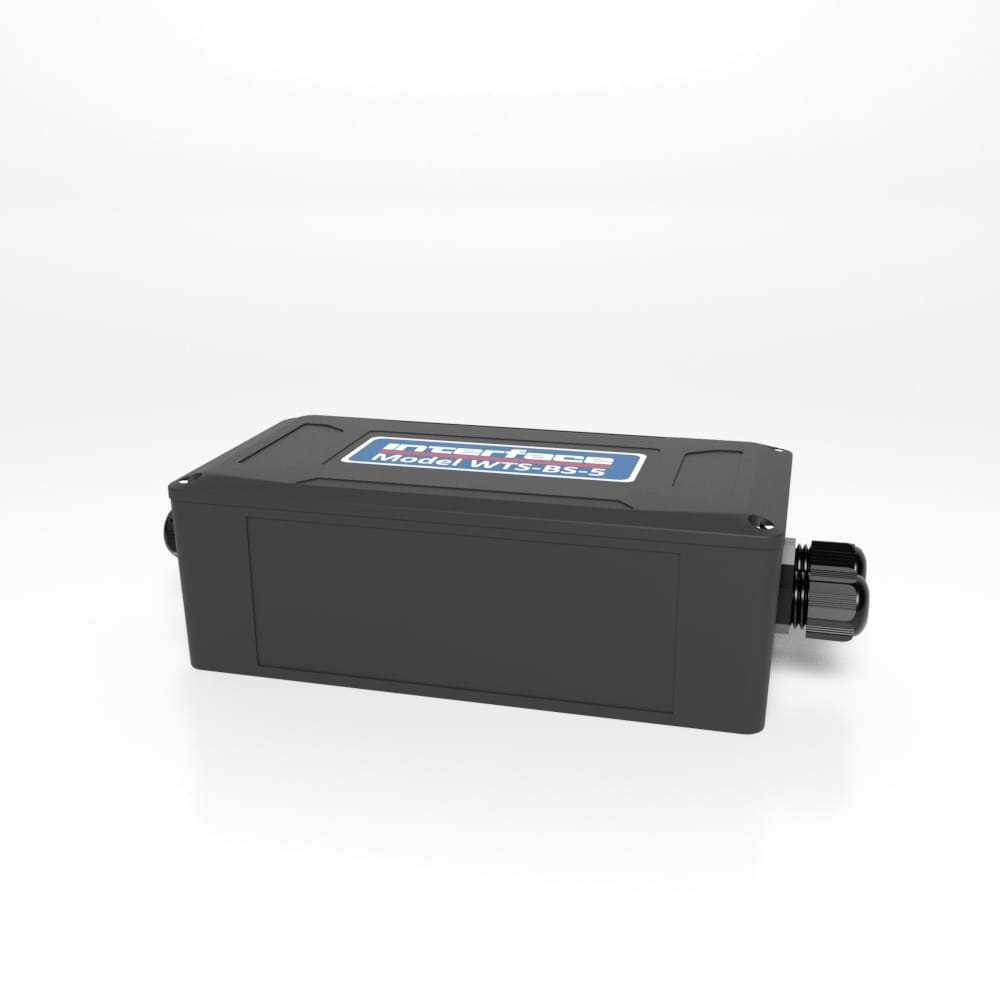
WTS-BS-2 Wireless Base Station with Industrial Interfaces
The pricing listed on our website is only for U.S. buyers and all pricing is subject to change without notice. Any inquiries for products from buyers outside of the U.S. will receive a quote and availability from the licensed distributor nearest your region. These prices will be based on product availability, currency conversions, markets, taxes, shipping costs, as well as local support.

The WTS-BS-2 is one of a range of base stations that are required for configuration and calibration of the WTS modular telemetry system. Base stations can also be used for data collection systems by making available the WTS wireless transmitter data over the industrial interfaces.
The data sent by transmitter modules can be utilized by multiple receivers such as displays, handheld readers, analog outputs, relay modules and computer interfaces. Receivers support common industrial power supplies and are available in robust IP rated enclosures with internal antennas optimized to give outstanding coverage.
The WTS-BS-2 supports USB, RS232 and RS485 connectivity. On Windows PCs the free WTS Toolkit is used to configure and calibrate the WTS modular telemetry system while the free WTS logging and visualization software allows monitoring and data collection.
The WTS-BS-2 is one of a range of base stations that are required for configuration and calibration of the WTS modular telemetry system. Base stations can also be used for data collection systems by making available the WTS wireless transmitter data over the industrial interfaces.
U.S. dimensions and capacities are provided for conversion only. Standard products have International System of Units (SI) capacities and dimensions.
U.S. dimensions and capacities are provided for conversion only. Standard products have International System of Units (SI) capacities and dimensions.
These base stations simply connect to the USB port of a PC and are powered from the USB bus.
This diagram shows the available connections, switches and LEDs.a
Switch positions 1 to 4 select the base station Address. This should normally be 1.
| Address | 1 | 2 | 3 | 4 |
| 1 | Off | Off | Off | Off |
| 2 | On | Off | Off | Off |
| 3 | Off | On | Off | Off |
| 4 | On | On | Off | Off |
| 5 | Off | Off | On | Off |
| 6 | On | Off | On | Off |
| 7 | Off | On | On | Off |
| 8 | On | On | On | Off |
| 9 | Off | Off | Off | On |
| 10 | On | Off | Off | On |
| 11 | Off | On | Off | On |
| 12 | On | On | Off | On |
| 13 | Off | Off | On | On |
| 14 | On | Off | On | On |
| 15 | Off | On | On | On |
| 16 | On | On | On | On |
Switch positions 5 to 7 set whether serial or USB is used. If USB is not selected then the chosen switch settings control the baud rate for the serial interface. Whether the serial interface is RS485 or RS232 is selected by switch position 8.
| Baud Rate / USB | 5 | 6 | 7 |
| USB | Off | Off | Off |
| 9600 | On | Off | Off |
| 19200 | Off | On | Off |
| 38400 | On | On | Off |
| 57600 | Off | Off | On |
| 115200 | On | Off | On |
| 230400 | Off | On | On |
| 460800 | On | On | On |
A baud rate of 9600 (and in some cases 19200) is not suitable for 2 way communication with remote modules as it is too slow and causes timeouts. This baud rate has been in-cluded to enable the base station to be connected to a 9600 baud device to allow low rate Data Provider packets to be received.
At any rate below 230400 is may be possible to lose packets at high data rates as the serial connection cannot keep pace with the radio transmissions.
If USB is not selected as the interface (Switch positions 5 to 7) then this switch position selects whether the serial interface is RS232 or RS485.
| 232/485 | 8 |
| RS232 | Off |
| RS485 | On |
USB base stations will be powered by the USB bus. If RS232 or RS485 are selected then external power will need to be connected to J4 on the –V and +V pins.
Two LEDS indicate Power/Mode and Activity.
The red LED indicates mode and should flash at a 2Hz rate. If any errors are detected with the radio then the LED will remain lit.
The green LED flashes once for each packet received or transmitted via radio, USB or serial.
The RS232 interface uses TX, RX and GND to connect to a PC, PLC etc. and uses standard RS232 voltage levels.
The baud rate can be selected by setting the DIP switches stated above.
The base station will require power cycling to utilize a baud rate change.
For more information visit Electrical Wiring Diagrams
| Dimensions | 3.30 × 6.50 × 2.20 in |
|---|
U.S. dimensions and capacities are provided for conversion only. Standard products have International System of Units (SI) capacities and dimensions.
U.S. dimensions and capacities are provided for conversion only. Standard products have International System of Units (SI) capacities and dimensions.
These base stations simply connect to the USB port of a PC and are powered from the USB bus.
This diagram shows the available connections, switches and LEDs.a
Switch positions 1 to 4 select the base station Address. This should normally be 1.
| Address | 1 | 2 | 3 | 4 |
| 1 | Off | Off | Off | Off |
| 2 | On | Off | Off | Off |
| 3 | Off | On | Off | Off |
| 4 | On | On | Off | Off |
| 5 | Off | Off | On | Off |
| 6 | On | Off | On | Off |
| 7 | Off | On | On | Off |
| 8 | On | On | On | Off |
| 9 | Off | Off | Off | On |
| 10 | On | Off | Off | On |
| 11 | Off | On | Off | On |
| 12 | On | On | Off | On |
| 13 | Off | Off | On | On |
| 14 | On | Off | On | On |
| 15 | Off | On | On | On |
| 16 | On | On | On | On |
Switch positions 5 to 7 set whether serial or USB is used. If USB is not selected then the chosen switch settings control the baud rate for the serial interface. Whether the serial interface is RS485 or RS232 is selected by switch position 8.
| Baud Rate / USB | 5 | 6 | 7 |
| USB | Off | Off | Off |
| 9600 | On | Off | Off |
| 19200 | Off | On | Off |
| 38400 | On | On | Off |
| 57600 | Off | Off | On |
| 115200 | On | Off | On |
| 230400 | Off | On | On |
| 460800 | On | On | On |
A baud rate of 9600 (and in some cases 19200) is not suitable for 2 way communication with remote modules as it is too slow and causes timeouts. This baud rate has been in-cluded to enable the base station to be connected to a 9600 baud device to allow low rate Data Provider packets to be received.
At any rate below 230400 is may be possible to lose packets at high data rates as the serial connection cannot keep pace with the radio transmissions.
If USB is not selected as the interface (Switch positions 5 to 7) then this switch position selects whether the serial interface is RS232 or RS485.
| 232/485 | 8 |
| RS232 | Off |
| RS485 | On |
USB base stations will be powered by the USB bus. If RS232 or RS485 are selected then external power will need to be connected to J4 on the –V and +V pins.
Two LEDS indicate Power/Mode and Activity.
The red LED indicates mode and should flash at a 2Hz rate. If any errors are detected with the radio then the LED will remain lit.
The green LED flashes once for each packet received or transmitted via radio, USB or serial.
The RS232 interface uses TX, RX and GND to connect to a PC, PLC etc. and uses standard RS232 voltage levels.
The baud rate can be selected by setting the DIP switches stated above.
The base station will require power cycling to utilize a baud rate change.
For more information visit Electrical Wiring Diagrams
| Dimensions | 3.30 × 6.50 × 2.20 in |
|---|

 BSC1-HD Single Channel PC Interface Module with Analog Output
