
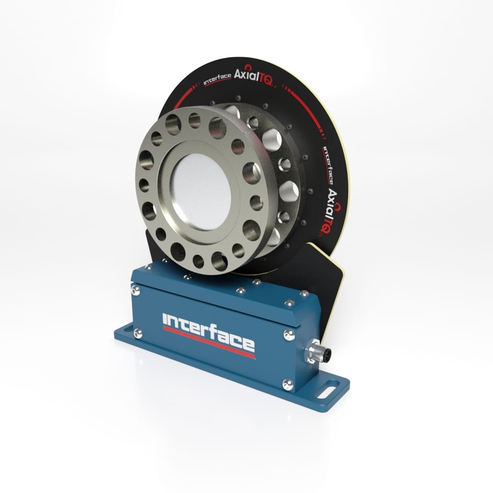


Features and Benefits
- Crash-Proof Design for Maximum Reliability
- Versatile Design for Application Flexibility
- Flexible Configuration
- Simultaneous Analog and Digital Outputs Enables Real-time Control and Data Collection
- Interchangeable Stators and Output Modules to Minimize Parts Inventory
- Wide Range of Standard Components to Match Any Application
Options
- Balanced Rotor to G2.5
- Speed Sensing 60 PPR
- High Resolution Encoder
- Integrated Couplings
In-Line Magnetic Encoder Kit Features and Benefits
- High resolution: <0.125°
- ±1 Increment Repeatability
- Quadrature Differential Signal Output (A, A/, B, B/)
- With Index Signal (I, I/)
- Line Driver (RS422)


 Dual Motor Dynamometer

