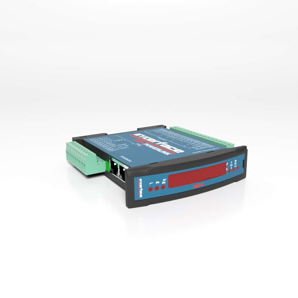
INF4 Two, Three, and Four Sensor Weight Transmitter and Indicator
Two, Three, and Four Sensor Weight Transmitter and Indicator
The INF4 Two, Three, and Four Sensor Weight Transmitter and Indicator is a versatile, multi-channel solution designed for precise summing and control of up to four load cell inputs, with the capability to power up to 16 load cells via junction boxes. It delivers a stable summed output while incorporating digital filtering to minimize weight oscillation and advanced calibration options, including theoretical and real calibration with up to five-point linearization for enhanced accuracy. Standard functions such as tare, semi-automatic zero, and automatic zero at power-on ensure reliable, repeatable measurements, while excitation remote sense improves signal integrity in demanding installations.
Designed for seamless integration, the INF4 supports PLC connectivity via analog output or a wide range of industrial fieldbus protocols, along with RS485 communication using Modbus RTU or ASCII. It features three relay outputs for setpoint control and two optoisolated inputs for system status monitoring. The six-digit red LED display, indicator LEDs, and front-panel keys provide straightforward setup and operation, while its compact DIN rail or panel-mount design simplifies installation.
Included Instrument Manager software enhances functionality with digital equalization, load distribution monitoring, automatic diagnostics, and event logging of key system activities. The INF4 is available with multiple communication options, including CANopen, DeviceNet, CC-Link, PROFIBUS DP, Modbus/TCP, Ethernet TCP/IP, EtherNet/IP, PROFINET IO, EtherCAT, POWERLINK, and SERCOS III, enabling it to operate as a slave or device across virtually any industrial automation network for scalable, high-performance weighing and process control applications.
The INF4 Two, Three, and Four Sensor Weight Transmitter and Indicator is a versatile, multi-channel solution designed for precise summing and control of up to four load cell inputs, with the capability to power up to 16 load cells via junction boxes.
Please Login to view pricing and product downloads Need a quote or looking to purchase this item?
Login, scroll to see your model descriptions and SKU part number, then use the Request for Quote button to submit your request.
Features and Benefits
- Includes Instrument Manager Software which provides: monitoring and direct management of individual load cells. (Does NOT display individual load values).
- Digital Equalization.
- 4 channel load distribution signaling with archive backups.
- Automatic Diagnostics can make comparisons between recorded values and display an alert if significant variations between the values are detected.
- Event Log archives data in chronological order of the last 50 events related to calibrations, zero settings, errors and equalizations.
- Connection to:
- PLC via analog output or fieldbus.
- PC/PLC via RS485 (Up to 99 instruments with line repeaters, up to 32 without line repeaters).
- Instrument Manager PC Software can connect to one INF4 at a time via RS485.
- Remote display via RS485.
- Excitation Remote Sense.
- Can Power Up to 16 Load Cells.
- Available Fieldbus Protocol Options.
- Digital Filter to reduce the effects of weight oscillationTheoretical calibration and real calibration with the possibility of weight linearizion up to 5 points.
- Tare weight zero setting.
- Automatic zero setting at power on.
- Semi-automatic tare (net/gross weight) and predetermined tare
- Semi-automatic zero.
- Direct connection between RS485 and RS232 without converter.
Standard Configuration
- RS485 serial port for communication via Modbus RTU protocol, ASCII bidirectional or continuous one way transmission.
- 3 relay logic outputs controlled by setpoint values or via protocols.
- 2 optoisolated PNP logic inputs: status reading via serial communication protocols.
- 4 load cell dedicated input SUMMED output from up to 4 load cells.
- Back panel mounting on Omega/DIN rail or front panel (except PROFIBUS DP version) with fixing kit included (panel drilling template 23×96 mm; panel thickness 2.5 mm).
- Dimensions: 26x115x120 mm.
- Six-digit red LED semi-alphanumeric display (8 mm height), 7 segment.
- Six indicator LED.
- Four buttons for system calibration.
- Extractable screw terminal boards.
Specifications
Specifications
U.S. dimensions and capacities are provided for conversion only. Standard products have International System of Units (SI) capacities and dimensions.V
Dimensions
Dimensions
U.S. dimensions and capacities are provided for conversion only. Standard products have International System of Units (SI) capacities and dimensions.
Connector Pin Diagram
Electrical Connections
Basic Information
- It is recommended that the power supply negative pole be grounded.
- It is possible to supply up to 16 350 ohm load cells.
- For 4-wire load cells, make a jumper between EX- and REF- and between EX+ and REF+. Connect terminal “- SUPPLY” to the RS485 common of the connected instruments in the event that these receive alternating current input or that they have an optically isolated RS485.
- In case of an RS485 network with several devices, it is recommended to activate the 120 ohm termination resistance on the two devices located at the ends of the network.
Wiring Diagram
In case of difficulty connecting all the reference wires of the installed load cells, simply connect those of the load cell located at the average distance from the instrument. The reference wires not used must be individually isolated.
USE OF 4-WIRE LOAD CELLS: if all the load cells used are 4-wire, make a jumper between -EX (26) and -REF (22) and between +EX (25) and +REF (21).
Terminals Legend
INF4 Legend
| 1 | OUTPUT No. 1 |
| 2 | OUTPUT No. 2 |
| 3 | OUTPUT No. 3 |
| 4 | OUTPUT COMMON |
| 5 | INPUT No. 1 (+VDC min 5 V max 24 V) |
| 6 | INPUT No. 2 (+VDC min 5 V max 24 V) |
| 7 | INPUT COMMON (-VDC 0 V) |
| 8 | +SUPPLY (12/24 VDC) |
| 9 | -SUPPLY (12/24 VDC) RS485: SHIELD, GND |
| 10 | +ANALOG OUTPUT 0-20 or 4-20 mA |
| 11 | +ANALOG OUTPUT 0-10 V |
| 12 | -ANALOG OUTPUT COMMON |
| 15 | +LOAD CELL 1 SIGNAL |
| 16 | -LOAD CELL 1 SIGNAL |
| 17 | +LOAD CELLS 1 and 2 EXCITATION (+EX) |
| 18 | -LOAD CELLS 1 and 2 EXCITATION (-EX) LOAD CELLS SHIELD |
| 19 | +LOAD CELL 2 SIGNAL |
| 20 | -LOAD CELL 2 SIGNAL |
| 21 | +LOAD CELLS REF/SENSE |
| 22 | -LOAD CELLS REF/SENSE |
| 23 | +LOAD CELL 3 SIGNAL |
| 24 | -LOAD CELL 3 SIGNAL |
| 25 | +LOAD CELLS 3 and 4 EXCITATION (+EX) |
| 26 | -LOAD CELLS 3 and 4 EXCITATION (-EX) LOAD CELLS SHIELD |
| 27 | +LOAD CELL 4 SIGNAL |
| 28 | -LOAD CELL 4 SIGNAL |
| 29 | RS485: + |
| 30 | RS485:- |
For more information visit Electrical Wiring Diagrams
Product Video