Dimensions
Dimensions
International System of Units (SI) dimensions and capacities are provided for conversion only. Standard products have U.S. capacities and dimensions. SI capacities available upon special request and at an additional cost.
Connector Pin Diagram
Overview
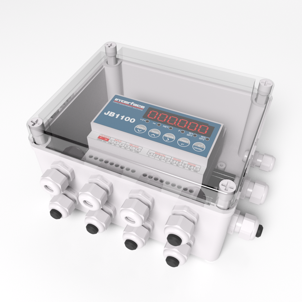
JB1100 Dimensions and Components JB1100 Wiring Table
| No. | Description |
| 1 | (+) 12-24 vdc power supply input |
| 2 | GND power supply input |
| 3 | Digital I/O |
| 4 | Analog output |
| 5 | Connection for serial line RS-485 |
| 6 | Connection for serial line RS-232 |
| 7 | Connections for load cell |
Note: For detailed call out of pin designations, See the Wiring Schematic below.
Electrical Precautionary Measures
Important:
The following electrical precautionary measures must be considered when installing this equipment:
- Main power supply must be maintained within ± 10% of the rated voltage.
- Electrical best practices must be observed by the installing technician.
- Follow recommended minimal separation distances given for cable categories, See the Maximum Cable Length below.
- The extension leads of the load cells, or signal amplifiers connecting to the serial ports and analog output, must be within stated maximum lengths, See the Maximum Cable Length below.
- It is recommended that load cell cables are shielded and run in conduit at an acceptable distance from power transmission lines to avoid signal interference and signal noise.
- All cable not in conduit or otherwise shielded should be of minimal length and terminated as close to conduit exit as possible to avoid extraneous signal noise.
- If the instrument is situated inside an electric panel, the power supply cable must be shielded and as short as possible, separate from every coil supply cable, inverter, electromotive force, and others. In addition, provide dedicated power supply to the instrument.
- Install RC filters on the contact coils, solenoid valves and all devices producing electric fields.
- It is recommended to leave the instrument powered on at all times to avoid condensation forming on the inside of the instrument.
Maximum Cable Length
Load Cell Cable
The maximum length of a standard load cell cable with sense wires is:
- 150′ at 30#AWG
- 300′ at 24#AWG
RS-232 Cable
The maximum length of the RS-232 cable is 50′ with a maximum baud rate of 19200.
RS-485 Cable
The maximum RS-485 cable length is 4000′, Refer to the JB1100 Technical Manual, Page 43 Section 6.3.
Analog Output Cable
The maximum length of the analog current output cable at 4-20mA is 300′.
The maximum length of the analog voltage output cable at 0-10vdc is 150′.
Grounding the System
A centrally located, single point ground, such as the ground bar of the electric panel, must be created and/or identified for proper grounding and functioning of the system. The ground must be sized so that the total resistance of grounding is lower than 10. Connect grounding points of all instrumentation, load cells, and weighing structure to this single point ground.
Load Cells and Junction Box
When the load cells are connected to the instrument through a junction box, the shielding of the load cell cables and the instrument must be connected to the junction box grounding.
When the load cells are directly connected to the instrument, the load cell cable shielding must be connected to the single point ground.
System cabling should be kept as short as possible to minimize noise potential. After exiting conduit or other shielding, a ferrite device should be used prior to conductor termination.
After platform and the load cell are properly grounded, connect the shield from the load cell cable to the instrument ground. See the Overview above.
Grounding ExampleImportant: Procedures not expressly described in this manual are considered improper use of the equipment.
Ensure the platform is level or the loading cells are shimmed evenly.
All connections must meet all local zone and environment standards.
Follow the recommended electrical precautionary measures described in the Electrical Precautionary Measures above.
Make sure that the grounding is made correctly, See the Grounding the System above.
Wiring Schematic
JB1100 Wiring Schematic
The CELL1 terminal board of the indicator can be connected to a six-wire load receiver (wiring must be jumpered if connecting to 4-wire load cell. See the Connection to the Load Cell below); CELL2, CELL3 and CELL4 are only for four-wire connection. See the Wiring Schematic above.
JB1100 Wiring Schematic Table
| Pin | Label | Description | | Pin | Label | Description | | Pin | Label | Description | | Pin | Label | Description |
| VE 12-24 Vdc Power Supply | | Analog Output | | Load Cell 1 | | Load Cell 3 |
| 1 | +vdc | +12-24 vdc | | Voltage | | 18 | SIG+ | Signal + | | 28 | SIG+ | Signal + |
| 2 | GND | 0vdc (GND) | | 9 | I+ | +20mA | | 19 | SIG- | Signal - | | 29 | SIG- | Signal - |
| Inputs and Outputs | | 10 | I- | -0mA (GND) | | 20 | SEN+ | Sense + | | 30 | EXC+ | Excitation + |
| Optoisolated Inputs Positive Logic (12-24vdc,5-20mA max) | | Current | | 21 | SEN- | Sense - | | 31 | EXC- | Excitation - |
| 3 | COM | Common Output | | 11 | v+ | +10v | | 22 | EXC+ | Excitation + | | Load Cell 4 |
| 4 | IN1 | Input 1 | | 12 | v- | 0v (GND) | | 23 | EXC- | Excitation - | | 32 | SIG+ | Signal + |
| 5 | IN 2 | Input 2 | | Serial Port | | Load Cell 2 | | 33 | SIG- | Signal - |
| Relays | | RS-485 | | 24 | SIG+ | Signal + | | 34 | EXC+ | Excitation + |
| 6 | RL1 | Relay 1 | | 13 | (A) 485 + Line | | 25 | SIG- | Signal - | | 35 | EXC- | Excitation - |
| 7 | RL2 | Relay 2 | | 14 | (B) 485 - Line | | 26 | EXC+ | Excitation + | | | | |
| 8 | COM | Common Relay | | RS-232 | | 27 | EXC- | Excitation - | | | | |
| | | | | 15 | TX | Transmission | | | | | | | | |
| | | | | 16 | RX | Reception | | | | | | | | |
| | | | | 17 | GND | Ground | | | | | | | | |
Note: The maximum resistance applicable on the output current is 350 Q and the minimum resistance applicable on the output voltage is 10 kQ.
Connection to the Load Cell
The load cell 1 terminal board of the JB1100 must be connected to the 6-wire load cell; if using a 4-wire load in the load cell 1 terminal board, cell excitation must jumper to sense, See the Jumpered 6-Wire Connect below. Load cells 2, 3, and 4 must be connected to 4-wire load cells, See the 4- and 6-Wire Connections below.
Important:
Sense is always enabled and, when not using 6-wire load cell, the sense terminals must be jumpered to the same polarity excitation wires.
Note: The sense compensates for drops in voltage along the cable that connects the instrument to the load cell. Voltage is lost when the instrument and the load cell are greater than 30ft apart. A cable is typically provided with a load cell. When exceeding the length of the provided load cell cable, six wires must be used to compensate for voltage drop. It is, however, recommended to never cut or shorten the load cell cable.
Jumpered 6-Wire Connect
4- and 6-Wire Connections
Input/Output Wiring
- Output power: 48 vac, 150mA max (or 60 vdc, 150mA max)
- Input voltage: 12vdc – 24 vdc max
- Input current: 5 mA min – 20 mA max
For more information visit Electrical Wiring Diagrams


 Rover Landing Gear

