Interface Mini™ Load Cell Selection Guide

This new Interface resource enables you to quickly evaluate the various load cell models based on whether you need a Load Button, Rod End, Load Washer, Beam Type, Pillow Block, S-Type, Single Point, or Pedal Type as well as their features and capabilities, including compression only, fatigue-rated, intrinsically safe, sealed, stainless steel, submersible, and tension and compression.

This tool will help choose the right mini load cell for your application with a range of capacities as low as 0.11 lbf / 0.5 N and as high as 100 kN. A variety of our load cells, can be used in an off-the-shelf application.

Interface Mini™ Load Cell Types and Options

Select Type of Mini Load Cell

Product Mini Load Cell Type

Product Mini Load Cell Features

Choose the selection criteria on the left and the Interface Mini™ load cell products that match your selections will appear below.

Interface’s mini load cells are used for light touch, light weight, and less space.

Our miniature load cells provide exceedingly accurate measurements similar to our LowProfile load cells that have our proprietary alloy strain gages. All our miniature beam load cell, miniature sensor, load button, load washer, tension force load cells, S-type load cells, and sealed stainless steel load cells can all be ordered in different sizes. Capacities are available as low as 0.11 lbf (0.5 N) and as high as 1,124K lbf (5,000kN). A variety of our miniature load cells are designed for off-the-shelf applications. Our engineers can also work with you to design custom load cells to fit your exact needs.

Load Button Cells

Many applications require the measurement of forces in a very confined space. The smaller LBM or LBS can fulfill the need for force measurements at a very respectable precision level that is sufficient for most applications.
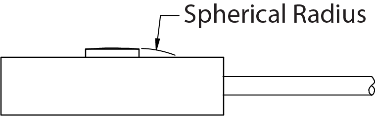
These miniature compression cells range in capacities from 10 lbf to 50,000 lbf. Diameters range from 1 inch to 3 inches, with heights from 0.39 inch to 1.5 inches. The shaped load button has a spherical radius to help confine misaligned loads to the primary axis of the cell.

Load Washer

Interface load washers come in a variety of sizes and capacities. With IDs as small as 0.1 inch (2.54mm) and as large as 8.1 inches (205mm), we are able to provide this product for a large number of applications. Max capacities range from 5 lbf (22N) to 1,124K lbf (5,000kN). Our Model LWCF is specifically designed for bolt testing. Our Models LWPF1 and LWPF2 are great for press force applications. We offer a number of other load washer models that can help in all type of solutions. Custom versions are available upon request.

Bending Beam Cell

The cell is bolted to a support through the two mounting holes. When you remove the covers, you can see the large hole bored through the beam. This forms thin sections at the top and bottom surface, which concentrate the forces into the area where the gages are mounted on the top and bottom faces of the beam. The gages may be mounted on the outside surface, as shown, or inside the large hole.
The compression load is applied at the end opposite from the two mounting holes, usually onto a load button that the user inserts in the loading hole. Interface MB Series load cells are available in capacities from 5 to 250 lbf. SSB series cells have a splash-proof sealing cover and come in sizes from 50 to 1,000 lbf.

Double Bending Beam Cell

A very useful variation on the bending beam design is achieved by forming two bending beams into one cell. This allows the loading fixtures to be attached at the threaded holes on the center line, between the beams, which makes the sensitive axis pass through the cell on a single line of action. In general, this configuration is much more user-friendly because of its short vertical dimension and compact design.
The SML Series load cells are available in capacities from 5 to 2,000 lbf. The 5 and 10 lbf cells can also be ordered with tension/compression overload protection, which makes them very useful for applications in which they could by damaged by an overload.

Shear Beam Cell

From the outside, a shear beam cell might look identical to a bending beam cell, but the theory of operation is entirely different. When the covers are removed we can see that the large hole, instead of passing all the way through the cell, is actually bored part of the way through from either side, leaving a thin, vertical web in the center of the cell.
The shear beam design is used in larger capacity beam cells that are more compact. Mounting of either cell is similar because there is considerable moment loading on the mounting end of the beam, the larger capacities require Grade 8 mounting bolts to provide enough tensile strength to withstand the forces under full load.

S-Beam Cells

Interface offers the most extensive selection of S-type Load Cells in the market. Capacities range from as low as 5 lbf (22N) to as high as 10K lbf (50kN) . The different types offered are standard (Models SM, SSM and SSM2), miniature (Models SMTM and SMA), Intrinsically Safe (Model SSMH), Overload Protected (Model SMT), Fatigue Rated (Model SSMF), Low Height (Model SML) and High Temperature (Model SSM-FDH). Nonlinearity is as low as +/-0.03% so these can be used in applications that require high accuracy. Sealed versions and high temperature versions are available if use in tough environments are needed.
The SM Series are accurate low-cost cell with straight-through loading design. The SSM Series is a rugged S-cell with splash-proof covers. Either series gives exceptional results in applications that can be designed so as to operate the cells in tension.
Although the forces on the gaged area appear the same as in a bending beam cell, the theory of operation is slightly different because the two ends of the “S” bend back over center, and the forces are applied down through the center of the gaged area.

Overload Protected S-Cell

The incorporation of overload protection is a major innovation in S-Cell design. By removing the large gaps at the top and bottom, and replacing them with small clearance gaps and locking fingers, the whole cell can be made to “go solid” in either mode (tension or compression) before the deflection of the gaged area exceeds the allowed overload specification. The double-stepped shape of the gaps is necessary to ensure that overload protection operates in both modes.
The SMT Series is ideally suited for applications that may generate forces as high as eight times the rating of the load cell. The two loading holes are vertically aligned, which makes the cell easy to design into machines that apply reciprocating or linear motion, either from a rotating crank or from a pneumatic or hydraulic cylinder.
The covers provide physical protection for the flexure, but the cell is not sealed.The SMT Series is especially suited for use in laboratories or medical facilities where large loads could be applied accidentally by untrained or non-technical personnel.

Single Point Impact Cell

Although the SPI resembles competing weigh pan cells, it was specifically designed to have greater than normal deflection at full scale in order to provide for the addition of stops to protect the cell against compression overloads. This was necessary because the usual deflection of 0.001 inch to 0.006 inch of most load cells is much too small to allow for the accurate adjustment of an external stop to protect the load cell.
SPI cells with capacities of 3 lbf, 7.5 lbf, and 15 lbf contain their own internal compression overload stop, which is adjusted at the factory to protect the cell up to four times the rated capacity. These cells have an additional bar under the lower surface, to provide a mount for the internal compression stop screw. Capacities of 25 lbf, 50 lbf, 75 lbf, and 150 lbf can be protected by placing hard stops under the corners of a weigh pan to catch the pan before excessive deflection damages the SPI cell.

The cell mounts to the scale frame on the step at the lower left corner, while the scale pan is mounted on the upper right corner with its load centroid over the primary axis at the center of the cell.

The center bar, containing the gages, is a bending beam. It is supported by the outer frame containing four thin flexure points, two on the top and two on the bottom, to provide mechanical strength for side loads and moment loads. This construction provides the superior moment canceling capability of the SPI, which ensures a consistent weight indication anywhere within the weigh pan size limits.

The SPI is also very popular with universities and test labs for its precision and ruggedness. It is also very convenient for lab use. Fixtures and load pans can be mounted easily on the two tapped holes on the top corner.